A hydraulic hub dynamometer tests a vehicle by coupling dynamometer pods directly to its driven wheel hubs and using hydraulic machinery to apply load. With the road wheels removed, each hub turns a pump in or connected to a pod. The pump moves hydraulic fluid against a controlled load, converting mechanical work into fluid power and ultimately heat. The system measures speed and torque directly or estimates torque using a calibrated hydraulic model, depending on the design.
The gearbox and final drive remain between the engine and the measuring point. Tyre-to-roller slip and tyre deformation are absent, but the result is still hub output rather than a direct engine-crankshaft measurement. This article concerns hydraulic pump loading at the vehicle hub; see Hub dynamometers for other types.
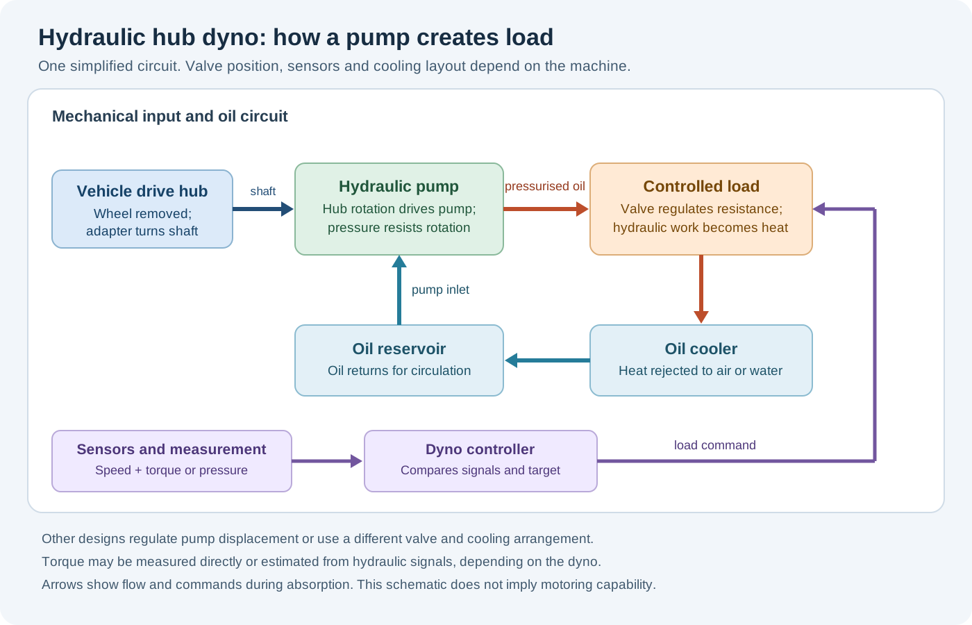
How the hydraulic load is produced
- Hub connection: the road wheel is removed and a suitable adapter couples the vehicle hub to the dyno input. The gearbox and differential turn this input when the vehicle drives the coupled axle.
- Hydraulic pump: hub rotation drives a pump which moves hydraulic oil through a circuit. A controlled resistance to that flow creates pressure difference across the pump and a resisting torque at its input.
- Load control: depending on the design, a control valve or other hydraulic control varies the load. A controller can adjust the command from measured speed or torque to hold a supported test point or follow a chosen sweep.
- Heat rejection: the absorbed energy becomes heat in the pump and hydraulic circuit. A cooler transfers that heat to air or to a separate cooling-water circuit; the actual plumbing, reservoir and controls differ between machines.
- Measurement: sensors record hub speed and either direct torque or the hydraulic variables needed by the particular calibrated calculation. The software displays and records results using the configured measurement and correction method.
The diagram is an illustrative circuit, not a plumbing diagram for every Dynapack or ROTOTEST unit. A ROTOTEST-assigned patent application describes one hub-driven pump, controlled outlet and tank arrangement with pump reaction measured by a load cell; commercial implementations and measurement systems can differ.
Torque, speed and power
At a particular rotating shaft, mechanical power is P = T × ω, where torque T is in newton metres and angular speed ω is in radians per second. In common units, power (kW) = torque (N·m) × speed (rpm) ÷ 9,549.3. For multiple pods, calculate each shaft's power using its own speed and torque at the same instant, then add the signed powers as appropriate.
A system can use an in-line torque transducer or a reaction arm and load cell. Another system may infer output from hydraulic pressure and a calibrated pump model. The hydraulic power carried by a flow is approximately Δp × Q, using pressure difference Δp in pascals and flow Q in cubic metres per second. It is not automatically identical to shaft power: leakage, pump efficiency, friction and measurement locations matter. For illustration, 200 bar across a flow of 60 litres per minute represents 20 kW of hydraulic power; the shaft input also covers losses. See Parker's hydraulic pump formulas.
The Dyna Tune description of its Dynapack describes hub-driven pumps with pressure and axle-speed measurement. By contrast, the manufacturer’s ROTOTEST VPA-RX88 datasheet specifies a front-end torque transducer and a separate speed sensor, with torque measurement independent of absorption. Do not assume the two measurement methods are identical.
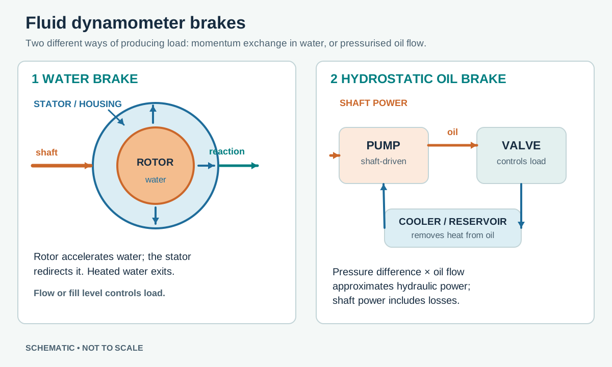
Hydraulic pump versus water brake
In the pump arrangement above, hydraulic oil transfers energy through a pressurised circuit and a controlled load. A water brake instead uses momentum exchange and turbulence as water circulates between a rotor and stator. A hydraulic-oil system may use water to cool oil in a heat exchanger; that does not make the absorber a water brake. Some hydraulic installations use air cooling instead. The two designs below are simplified examples. See water and oil hydraulic dynamometer brakes.
Makes and models
The following are the hydraulic hub-dyno families established by the cited sources. They are examples rather than a complete historical inventory; manufacturer, generation, options and current availability must be checked for the actual machine.
Dynapack hydraulic hub dynos
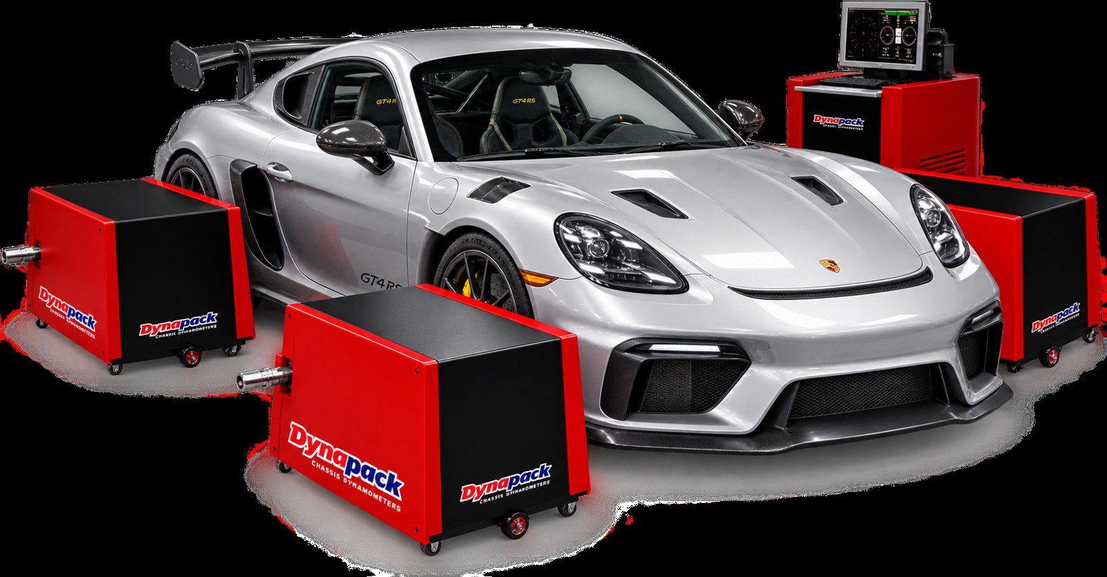
Dynapack describes a modular range with DAQ3, DAQ4 and DAQ5 two-wheel-drive configurations. Its model range lists 4WD combinations including DAQ33, DAQ43, DAQ44, DAQ53, DAQ54 and DAQ55. Two axle systems can be combined; consult the manufacturer for the exact combination, adapters and torque–speed envelope. The manufacturer photograph below shows a four-pod installation; the exact DAQ model is not identified in the image source.
Earlier ROTOTEST hydraulic hub dynos
The earlier ROTOTEST VPA-RX family is a documented hydraulic example. The VPA-RX88 4WD datasheet lists multi-gear pumps, a hydraulic common rail and fast valve, separate front-end torque transducers and speed sensors, and DynoVision and Datmon software. It describes Hurricane cooling units and an air-cooled system for that configuration. Those details apply to the documented RX88, not automatically to all ROTOTEST generations. A historic HUBDYNO 1005 installation was reported as hydraulic; a 2014 report describes SuperFlow as the US distributor of the Swedish ROTOTEST product, rather than as a separate manufacturer. ROTOTEST RX88 datasheet; 2014 distributor report; HUBDYNO 1005 example.
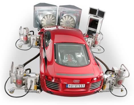

Later ROTOTEST Energy systems use electric four-quadrant machines. A hydraulic VPA or HUBDYNO and an electric Energy system should not be treated as the same absorber design.
Control, testing and limitations
With sufficient absorber torque and cooling, feedback control can hold a supported hub speed for steady-state mapping or regulate the rate of a sweep. Available load changes with hub speed, pressure, pump displacement, fluid temperature and equipment limits. A passive hydraulic absorber cannot be assumed to motor the vehicle; a separate powered capability must be designed into the machine. An oil cooler can use air or water as its secondary cooling medium.
For four-wheel drive, the operator must use the correct number of pods and control arrangement for the vehicle's differentials, clutches and electric axles. Individual hub-speed control or torque-vectoring simulation exists on some systems, not necessarily every model or software version. Follow the equipment and vehicle manufacturers' procedures.
When specifying or checking a system, record adapter and fastener compatibility, permissible axle weight and hub torque, speed and continuous-duty limits, pressure and oil temperature, cooling requirements, control mode, sensor and calibration method, correction standard and gear. Compare repeat runs under consistent conditions; do not equate coastdown-estimated crank power with direct engine-dyno measurement. See measurement and interpreting results and test setup and safety.
Related: Dynamometers overview · Hub dynamometers · Dynamometer control systems · Dynapack · ROTOTEST.
Related: Eddy-current hub dynamometers — operating principles, diagrams and manufacturer examples.
Related guide: Electric motor and regenerative hub dynamometers — operation, energy recovery and manufacturer examples.
Compare the options: Compare hydraulic, eddy-current and electric hub dynamometers.