Removed text is struck through; added text is highlighted.
An eddy-current hub dynamometer tests a vehicle by coupling load-absorbing units directly to its driven hubs, with the road wheels removed. Each unit uses an electrically controlled eddy-current brake to resist rotation. A controller adjusts the braking load while the system records torque and speed, allowing acceleration sweeps and, within the machine's operating envelope, steady-state tuning.
The gearbox and final drive remain in the power path; tyre-to-roller contact does not. Hub output is therefore neither a direct crankshaft measurement nor automatically identical to a rolling-road result. See Hub dynamometers for the overall layout.
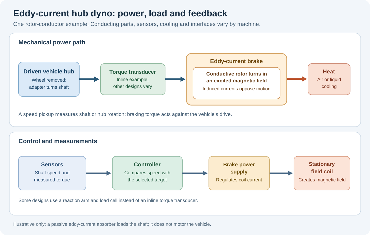
Simplified rotor-conductor example showing the hub drive, eddy brake, cooling and control feedback. Actual designs vary. Original schematic for Tuning Wiki, CC BY 4.0.
How the brake works
Drive: the vehicle hub turns a compatible adapter and the dyno's input shaft. Some installations use gearing between the hub and absorber.
Magnetic field: a controlled electrical current energises a coil in the brake. Relative motion between the magnetic field and conductive material induces circulating electrical currents, called eddy currents.
Resisting torque: the induced currents produce their own magnetic field. Its interaction with the original field opposes the relative motion, resisting hub rotation. The illustration shows currents in a rotating conductor; other brake constructions induce them in stationary conductive parts as rotor teeth pass. The exact magnetic circuit varies.
Heat removal: electrical resistance converts absorbed mechanical energy largely into heat in the brake. Cooling carries the heat away. An air-cooled unit rejects heat to airflow; some other eddy-current brakes use water cooling. Cooling water does not make the machine a hydraulic water brake.
Feedback: torque and speed measurements go to the control system, which changes coil excitation to regulate load or speed. The circuit uses electrical power for excitation and controls; the absorbed shaft power is dissipated as heat rather than normally returned to the grid.
The Magtrol WB/PB manual describes eddy-current construction, torque measurement and operating limits; its component-dyno design is an example of the principle, not a diagram of every automotive hub unit. See also the general eddy-current brake guide.
Typical two-wheel-drive hub layout. Both driven hub outputs are measured and their powers combined. Original schematic created for Tuning Wiki; individual equipment arrangements vary.
Measuring torque, speed and power
One common method mounts the absorber so its reaction force acts on a calibrated load cell through a known arm. A speed pickup measures rotation. Other equipment uses an in-line torque transducer or a different calibrated arrangement. If gearing separates the absorber and hub, torque and speed must be converted consistently, including applicable losses and calibration.
At the same shaft and instant, power (kW) = torque (N·m) × speed (rpm) ÷ 9,549.3. Calculate each hub's power using that hub's torque and speed, then add simultaneous signed powers as appropriate. Do not multiply hub torque by engine rpm without correctly converting the measurement. The vehicle's gearing changes the relationship between engine and hub torque and speed.
During a sweep, some torque accelerates the dyno's own rotating parts. A brake reaction reading alone may omit that component; compensation and reporting vary with the equipment. Record the gear, test mode, temperature, correction standard and sensor calibration before comparing results. See measurement and interpreting results and the Dynolyze user manual.
Control, cooling and limits
The controller receives the operator's speed, load or sweep demand and adjusts coil current using feedback. With sufficient braking torque and cooling at the chosen speed, it can hold a steady operating point for fuel and ignition mapping; a sweep changes speed through a range. Available modes and individual hub control depend on the controller and software. See dynamometer control systems and Rotronics Hubscan documentation.
Eddy-current braking torque falls to zero at standstill and is generally reduced at low speed. A maximum power or torque headline does not describe the complete speed range: consult the actual torque–speed curve, peak duration and continuous thermal rating. Keep cooling passages clear and follow the maker's temperature and duty-cycle limits. A passive eddy-current brake absorbs power; it does not drive the vehicle like a suitably equipped motor/generator system.
Use the correct hub adapters, fasteners, guards, support and restraint arrangements specified by the machine manufacturer. Provide vehicle cooling and exhaust extraction as well as brake cooling. For four-wheel-drive vehicles, use the appropriate number of units and observe vehicle and dyno instructions for differentials, clutches and traction systems. See test setup and safety.
Manufacturers and models
These are examples of eddy-current hub products rather than a complete list. Capabilities, dimensions, adapters, controller options and availability vary by model and generation; check the current specification with the supplier. Photographs are manufacturer or supplier images used with permission.
Advanced Dyno Solutions hub dynos
Advanced Dyno Solutions supplies 2WD and 4WD hub systems using eddy-current absorbers. Select the configuration, control system and adapters for the vehicle and intended load; consult ADS for the exact specification.
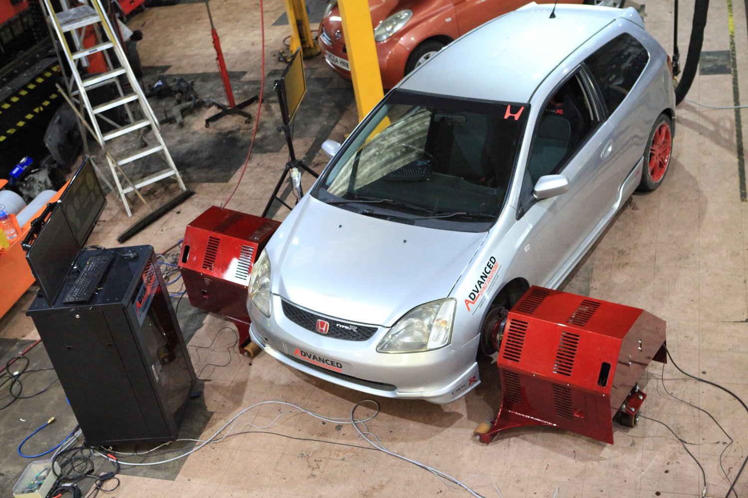
Advanced Dyno Solutions hub-dyno installation. Image: Advanced Dyno Solutions, used with permission.
Dynolyze SMALL, SMALL PLUS and MEDIUM
Dynolyze offers the SMALL, SMALL PLUS and MEDIUM hub families with different braking capacities and reach. Its model comparison lists per-hub braking torque and maximum hub speed; the published power figures are speed-dependent calculated values, so check the full test and cooling requirements. Two- and four-wheel-drive configurations are offered.
A pair of Dynolyze SMALL hub-dyno units. Image: Dynolyze, used with permission.
Rotronics Hubscan and Hubscan Plus
Rotronics Hubscan and Hubscan Plus are eddy-current hub systems supplied in configurations for different vehicle layouts. The manufacturer's Hubscan information and brochure describe the brake units and Dynascan control software. Check the particular model's specifications and axle configuration.
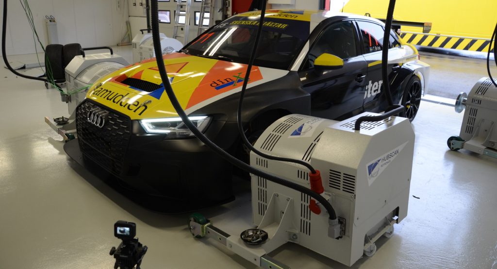
Rotronics Hubscan vehicle test installation; exact variant not established. Image: Rotronics, used with permission.
Dynocom AWD 2000 POD and AWD 4500
Dynocom describes its AWD 2000 POD package with four pods and four eddy-current brakes, supporting acceleration, sweep, step and steady-state tests. Its AWD 4500 series is another hub system. The manufacturer's figures have defined supply and test-duration conditions; do not treat maximum output as an unlimited continuous rating.
Dynocom AWD 2000 POD units shown around a car in a showroom. Image: Dynocom, used with permission.
Mainline DynoLog ProHub
Mainline DynoLog offers ProHub AWD CCS systems and the ProHub Extreme 2WD. Configurations differ in absorber capacity and arrangement; the Extreme is an example where two hub connections can use four brakes, so one brake per hub is not universal.
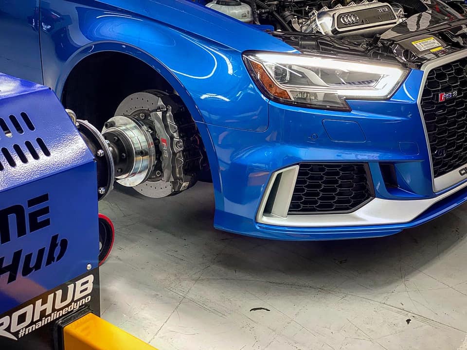
Car coupled to a Mainline ProHub unit; exact variant not established. Image: Mainline DynoLog, used with permission.
Magicmotorsport Dynomag Hub
Dynomag Hub is Magicmotorsport's eddy-current hub-dyno product, offered in two- and four-wheel-drive configurations. The product information describes the units and associated software. Confirm the configuration and available test modes with the supplier.
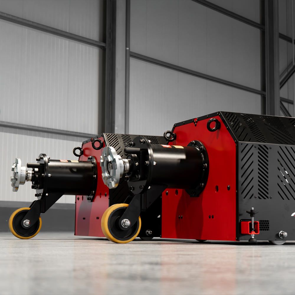
Two Dynomag Hub absorber units. Image: Magicmotorsport, used with permission.
Dynojet Vector-X4000 and Racetech Dynamics RTD Hub 2000
Dynojet's Vector-X4000 is a hub dyno whose installation manual describes eddy-current brakes, load-cell calibration, DynoWare RT electronics and Power Core software. Check the configuration against the version supplied. Racetech Dynamics' RTD Hub 2000 is marketed as a hub-dyno kit: check the supplier's current kit contents, compatible sensors, controller and power stage before treating it as a complete operational system.
Comparison with other hub dynos
A hydraulic hub dyno typically loads a hub-driven oil pump against a controlled hydraulic circuit. An eddy-current unit instead produces braking torque electromagnetically and rejects heat from the brake. A separate electric motor/generator hub system may be able to motor the drivetrain or regenerate, if designed for those functions. The location of the hub measurement is similar, but the loading, cooling and control hardware are different.
Related guide: Electric motor and regenerative hub dynamometers — operation, energy recovery and manufacturer examples.
Compare the options: Compare hydraulic, eddy-current and electric hub dynamometers.
Rendered revisions
Open each version to inspect formatting, tables and photographs.
Revision 4: Eddy-current hub dynamometers
An eddy-current hub dynamometer tests a vehicle by coupling load-absorbing units directly to its driven hubs, with the road wheels removed. Each unit uses an electrically controlled eddy-current brake to resist rotation. A controller adjusts the braking load while the system records torque and speed, allowing acceleration sweeps and, within the machine's operating envelope, steady-state tuning.
The gearbox and final drive remain in the power path; tyre-to-roller contact does not. Hub output is therefore neither a direct crankshaft measurement nor automatically identical to a rolling-road result. See Hub dynamometers for the overall layout.
Simplified rotor-conductor example showing the hub drive, eddy brake, cooling and control feedback. Actual designs vary. Original schematic for Tuning Wiki, CC BY 4.0.
How the brake works
Drive: the vehicle hub turns a compatible adapter and the dyno's input shaft. Some installations use gearing between the hub and absorber.
Magnetic field: a controlled electrical current energises a coil in the brake. Relative motion between the magnetic field and conductive material induces circulating electrical currents, called eddy currents.
Resisting torque: the induced currents produce their own magnetic field. Its interaction with the original field opposes the relative motion, resisting hub rotation. The illustration shows currents in a rotating conductor; other brake constructions induce them in stationary conductive parts as rotor teeth pass. The exact magnetic circuit varies.
Heat removal: electrical resistance converts absorbed mechanical energy largely into heat in the brake. Cooling carries the heat away. An air-cooled unit rejects heat to airflow; some other eddy-current brakes use water cooling. Cooling water does not make the machine a hydraulic water brake.
Feedback: torque and speed measurements go to the control system, which changes coil excitation to regulate load or speed. The circuit uses electrical power for excitation and controls; the absorbed shaft power is dissipated as heat rather than normally returned to the grid.
The Magtrol WB/PB manual describes eddy-current construction, torque measurement and operating limits; its component-dyno design is an example of the principle, not a diagram of every automotive hub unit. See also the general eddy-current brake guide.
Typical two-wheel-drive hub layout. Both driven hub outputs are measured and their powers combined. Original schematic created for Tuning Wiki; individual equipment arrangements vary.
Measuring torque, speed and power
One common method mounts the absorber so its reaction force acts on a calibrated load cell through a known arm. A speed pickup measures rotation. Other equipment uses an in-line torque transducer or a different calibrated arrangement. If gearing separates the absorber and hub, torque and speed must be converted consistently, including applicable losses and calibration.
At the same shaft and instant, power (kW) = torque (N·m) × speed (rpm) ÷ 9,549.3. Calculate each hub's power using that hub's torque and speed, then add simultaneous signed powers as appropriate. Do not multiply hub torque by engine rpm without correctly converting the measurement. The vehicle's gearing changes the relationship between engine and hub torque and speed.
During a sweep, some torque accelerates the dyno's own rotating parts. A brake reaction reading alone may omit that component; compensation and reporting vary with the equipment. Record the gear, test mode, temperature, correction standard and sensor calibration before comparing results. See measurement and interpreting results and the Dynolyze user manual.
Control, cooling and limits
The controller receives the operator's speed, load or sweep demand and adjusts coil current using feedback. With sufficient braking torque and cooling at the chosen speed, it can hold a steady operating point for fuel and ignition mapping; a sweep changes speed through a range. Available modes and individual hub control depend on the controller and software. See dynamometer control systems and Rotronics Hubscan documentation.
Eddy-current braking torque falls to zero at standstill and is generally reduced at low speed. A maximum power or torque headline does not describe the complete speed range: consult the actual torque–speed curve, peak duration and continuous thermal rating. Keep cooling passages clear and follow the maker's temperature and duty-cycle limits. A passive eddy-current brake absorbs power; it does not drive the vehicle like a suitably equipped motor/generator system.
Use the correct hub adapters, fasteners, guards, support and restraint arrangements specified by the machine manufacturer. Provide vehicle cooling and exhaust extraction as well as brake cooling. For four-wheel-drive vehicles, use the appropriate number of units and observe vehicle and dyno instructions for differentials, clutches and traction systems. See test setup and safety.
Manufacturers and models
These are examples of eddy-current hub products rather than a complete list. Capabilities, dimensions, adapters, controller options and availability vary by model and generation; check the current specification with the supplier. Photographs are manufacturer or supplier images used with permission.
Advanced Dyno Solutions hub dynos
Advanced Dyno Solutions supplies 2WD and 4WD hub systems using eddy-current absorbers. Select the configuration, control system and adapters for the vehicle and intended load; consult ADS for the exact specification.
Advanced Dyno Solutions hub-dyno installation. Image: Advanced Dyno Solutions, used with permission.
Dynolyze SMALL, SMALL PLUS and MEDIUM
Dynolyze offers the SMALL, SMALL PLUS and MEDIUM hub families with different braking capacities and reach. Its model comparison lists per-hub braking torque and maximum hub speed; the published power figures are speed-dependent calculated values, so check the full test and cooling requirements. Two- and four-wheel-drive configurations are offered.
A pair of Dynolyze SMALL hub-dyno units. Image: Dynolyze, used with permission.
Rotronics Hubscan and Hubscan Plus
Rotronics Hubscan and Hubscan Plus are eddy-current hub systems supplied in configurations for different vehicle layouts. The manufacturer's Hubscan information and brochure describe the brake units and Dynascan control software. Check the particular model's specifications and axle configuration.
Rotronics Hubscan vehicle test installation; exact variant not established. Image: Rotronics, used with permission.
Dynocom AWD 2000 POD and AWD 4500
Dynocom describes its AWD 2000 POD package with four pods and four eddy-current brakes, supporting acceleration, sweep, step and steady-state tests. Its AWD 4500 series is another hub system. The manufacturer's figures have defined supply and test-duration conditions; do not treat maximum output as an unlimited continuous rating.
Dynocom AWD 2000 POD units shown around a car in a showroom. Image: Dynocom, used with permission.
Mainline DynoLog ProHub
Mainline DynoLog offers ProHub AWD CCS systems and the ProHub Extreme 2WD. Configurations differ in absorber capacity and arrangement; the Extreme is an example where two hub connections can use four brakes, so one brake per hub is not universal.
Car coupled to a Mainline ProHub unit; exact variant not established. Image: Mainline DynoLog, used with permission.
Magicmotorsport Dynomag Hub
Dynomag Hub is Magicmotorsport's eddy-current hub-dyno product, offered in two- and four-wheel-drive configurations. The product information describes the units and associated software. Confirm the configuration and available test modes with the supplier.
Two Dynomag Hub absorber units. Image: Magicmotorsport, used with permission.
Dynojet Vector-X4000 and Racetech Dynamics RTD Hub 2000
Dynojet's Vector-X4000 is a hub dyno whose installation manual describes eddy-current brakes, load-cell calibration, DynoWare RT electronics and Power Core software. Check the configuration against the version supplied. Racetech Dynamics' RTD Hub 2000 is marketed as a hub-dyno kit: check the supplier's current kit contents, compatible sensors, controller and power stage before treating it as a complete operational system.
Comparison with other hub dynos
A hydraulic hub dyno typically loads a hub-driven oil pump against a controlled hydraulic circuit. An eddy-current unit instead produces braking torque electromagnetically and rejects heat from the brake. A separate electric motor/generator hub system may be able to motor the drivetrain or regenerate, if designed for those functions. The location of the hub measurement is similar, but the loading, cooling and control hardware are different.
An eddy-current hub dynamometer tests a vehicle by coupling load-absorbing units directly to its driven hubs, with the road wheels removed. Each unit uses an electrically controlled eddy-current brake to resist rotation. A controller adjusts the braking load while the system records torque and speed, allowing acceleration sweeps and, within the machine's operating envelope, steady-state tuning.
The gearbox and final drive remain in the power path; tyre-to-roller contact does not. Hub output is therefore neither a direct crankshaft measurement nor automatically identical to a rolling-road result. See Hub dynamometers for the overall layout.
Simplified rotor-conductor example showing the hub drive, eddy brake, cooling and control feedback. Actual designs vary. Original schematic for Tuning Wiki, CC BY 4.0.
How the brake works
Drive: the vehicle hub turns a compatible adapter and the dyno's input shaft. Some installations use gearing between the hub and absorber.
Magnetic field: a controlled electrical current energises a coil in the brake. Relative motion between the magnetic field and conductive material induces circulating electrical currents, called eddy currents.
Resisting torque: the induced currents produce their own magnetic field. Its interaction with the original field opposes the relative motion, resisting hub rotation. The illustration shows currents in a rotating conductor; other brake constructions induce them in stationary conductive parts as rotor teeth pass. The exact magnetic circuit varies.
Heat removal: electrical resistance converts absorbed mechanical energy largely into heat in the brake. Cooling carries the heat away. An air-cooled unit rejects heat to airflow; some other eddy-current brakes use water cooling. Cooling water does not make the machine a hydraulic water brake.
Feedback: torque and speed measurements go to the control system, which changes coil excitation to regulate load or speed. The circuit uses electrical power for excitation and controls; the absorbed shaft power is dissipated as heat rather than normally returned to the grid.
The Magtrol WB/PB manual describes eddy-current construction, torque measurement and operating limits; its component-dyno design is an example of the principle, not a diagram of every automotive hub unit. See also the general eddy-current brake guide.
Typical two-wheel-drive hub layout. Both driven hub outputs are measured and their powers combined. Original schematic created for Tuning Wiki; individual equipment arrangements vary.
Measuring torque, speed and power
One common method mounts the absorber so its reaction force acts on a calibrated load cell through a known arm. A speed pickup measures rotation. Other equipment uses an in-line torque transducer or a different calibrated arrangement. If gearing separates the absorber and hub, torque and speed must be converted consistently, including applicable losses and calibration.
At the same shaft and instant, power (kW) = torque (N·m) × speed (rpm) ÷ 9,549.3. Calculate each hub's power using that hub's torque and speed, then add simultaneous signed powers as appropriate. Do not multiply hub torque by engine rpm without correctly converting the measurement. The vehicle's gearing changes the relationship between engine and hub torque and speed.
During a sweep, some torque accelerates the dyno's own rotating parts. A brake reaction reading alone may omit that component; compensation and reporting vary with the equipment. Record the gear, test mode, temperature, correction standard and sensor calibration before comparing results. See measurement and interpreting results and the Dynolyze user manual.
Control, cooling and limits
The controller receives the operator's speed, load or sweep demand and adjusts coil current using feedback. With sufficient braking torque and cooling at the chosen speed, it can hold a steady operating point for fuel and ignition mapping; a sweep changes speed through a range. Available modes and individual hub control depend on the controller and software. See dynamometer control systems and Rotronics Hubscan documentation.
Eddy-current braking torque falls to zero at standstill and is generally reduced at low speed. A maximum power or torque headline does not describe the complete speed range: consult the actual torque–speed curve, peak duration and continuous thermal rating. Keep cooling passages clear and follow the maker's temperature and duty-cycle limits. A passive eddy-current brake absorbs power; it does not drive the vehicle like a suitably equipped motor/generator system.
Use the correct hub adapters, fasteners, guards, support and restraint arrangements specified by the machine manufacturer. Provide vehicle cooling and exhaust extraction as well as brake cooling. For four-wheel-drive vehicles, use the appropriate number of units and observe vehicle and dyno instructions for differentials, clutches and traction systems. See test setup and safety.
Manufacturers and models
These are examples of eddy-current hub products rather than a complete list. Capabilities, dimensions, adapters, controller options and availability vary by model and generation; check the current specification with the supplier. Photographs are manufacturer or supplier images used with permission.
Advanced Dyno Solutions hub dynos
Advanced Dyno Solutions supplies 2WD and 4WD hub systems using eddy-current absorbers. Select the configuration, control system and adapters for the vehicle and intended load; consult ADS for the exact specification.
Advanced Dyno Solutions hub-dyno installation. Image: Advanced Dyno Solutions, used with permission.
Dynolyze SMALL, SMALL PLUS and MEDIUM
Dynolyze offers the SMALL, SMALL PLUS and MEDIUM hub families with different braking capacities and reach. Its model comparison lists per-hub braking torque and maximum hub speed; the published power figures are speed-dependent calculated values, so check the full test and cooling requirements. Two- and four-wheel-drive configurations are offered.
A pair of Dynolyze SMALL hub-dyno units. Image: Dynolyze, used with permission.
Rotronics Hubscan and Hubscan Plus
Rotronics Hubscan and Hubscan Plus are eddy-current hub systems supplied in configurations for different vehicle layouts. The manufacturer's Hubscan information and brochure describe the brake units and Dynascan control software. Check the particular model's specifications and axle configuration.
Rotronics Hubscan vehicle test installation; exact variant not established. Image: Rotronics, used with permission.
Dynocom AWD 2000 POD and AWD 4500
Dynocom describes its AWD 2000 POD package with four pods and four eddy-current brakes, supporting acceleration, sweep, step and steady-state tests. Its AWD 4500 series is another hub system. The manufacturer's figures have defined supply and test-duration conditions; do not treat maximum output as an unlimited continuous rating.
Dynocom AWD 2000 POD units shown around a car in a showroom. Image: Dynocom, used with permission.
Mainline DynoLog ProHub
Mainline DynoLog offers ProHub AWD CCS systems and the ProHub Extreme 2WD. Configurations differ in absorber capacity and arrangement; the Extreme is an example where two hub connections can use four brakes, so one brake per hub is not universal.
Car coupled to a Mainline ProHub unit; exact variant not established. Image: Mainline DynoLog, used with permission.
Magicmotorsport Dynomag Hub
Dynomag Hub is Magicmotorsport's eddy-current hub-dyno product, offered in two- and four-wheel-drive configurations. The product information describes the units and associated software. Confirm the configuration and available test modes with the supplier.
Two Dynomag Hub absorber units. Image: Magicmotorsport, used with permission.
Dynojet Vector-X4000 and Racetech Dynamics RTD Hub 2000
Dynojet's Vector-X4000 is a hub dyno whose installation manual describes eddy-current brakes, load-cell calibration, DynoWare RT electronics and Power Core software. Check the configuration against the version supplied. Racetech Dynamics' RTD Hub 2000 is marketed as a hub-dyno kit: check the supplier's current kit contents, compatible sensors, controller and power stage before treating it as a complete operational system.
Comparison with other hub dynos
A hydraulic hub dyno typically loads a hub-driven oil pump against a controlled hydraulic circuit. An eddy-current unit instead produces braking torque electromagnetically and rejects heat from the brake. A separate electric motor/generator hub system may be able to motor the drivetrain or regenerate, if designed for those functions. The location of the hub measurement is similar, but the loading, cooling and control hardware are different.