Removed text is struck through; added text is highlighted.
The intake air temperature sensor (IAT) reports the temperature at its position in the intake system. The engine control unit (ECU) uses this information, alongside other measurements, for functions such as air-charge estimation, fuelling and engine protection. An implausible reading may come from the sensor, its wiring or calibration; a high reading may also reflect genuinely hot air or heat absorbed from the installation.
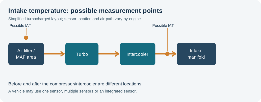
Possible temperature measurement positions in a simplified turbocharged intake. This is not a layout for a specific vehicle; not every engine has both sensors. Original Tuning Wiki illustration by OpenAI Codex, commissioned for use on Tuning Wiki. Technical basis: Bosch integrated intake pressure and temperature sensor.
Symptoms and first checks
ObservationWhat to investigate
Engine warning light or IAT codeRecord the full code, sensor number and freeze-frame data; check the correct circuit, connector, location and temperature reading.
Poor cold starting, uneven running or hesitationCompare temperatures after a cold soak and check the sensor circuit. Fuel, ignition, coolant temperature and air leaks can cause similar symptoms.
Reduced power or poor economyCheck whether the reported temperature is plausible and whether a protective strategy is active. Airflow, boost, fuel delivery and exhaust restrictions are other possibilities.
Very hot or cold value immediately after key-onInspect the circuit and identify the ECU’s fallback value. An extreme number can indicate an electrical fault but is not proof of a failed sensor.
High reading after a hot restart or under boostConsider sensor location, hot-soak conditions and actual charge-air temperature. Compare using an independent measurement before replacing parts.
Symptoms and ECU fallback strategies vary. HELLA’s IAT guidance describes temperature-dependent resistance and electrical checks. A temperature reading alone cannot establish the cause of a running fault.
Where is the sensor?
An IAT sensor can be a separate component in an intake duct or manifold, or it can share a housing with another sensor. Some mass-airflow meters incorporate intake temperature measurement; some manifold or boost-pressure sensors incorporate an IAT element, often called a combined pressure/temperature or TMAP sensor. More than one temperature sensor may be fitted. The diagnostic code and wiring diagram identify the relevant sensor, not the appearance of the housing alone. HELLA’s combined sensor information and Bosch’s pressure/temperature description provide examples.
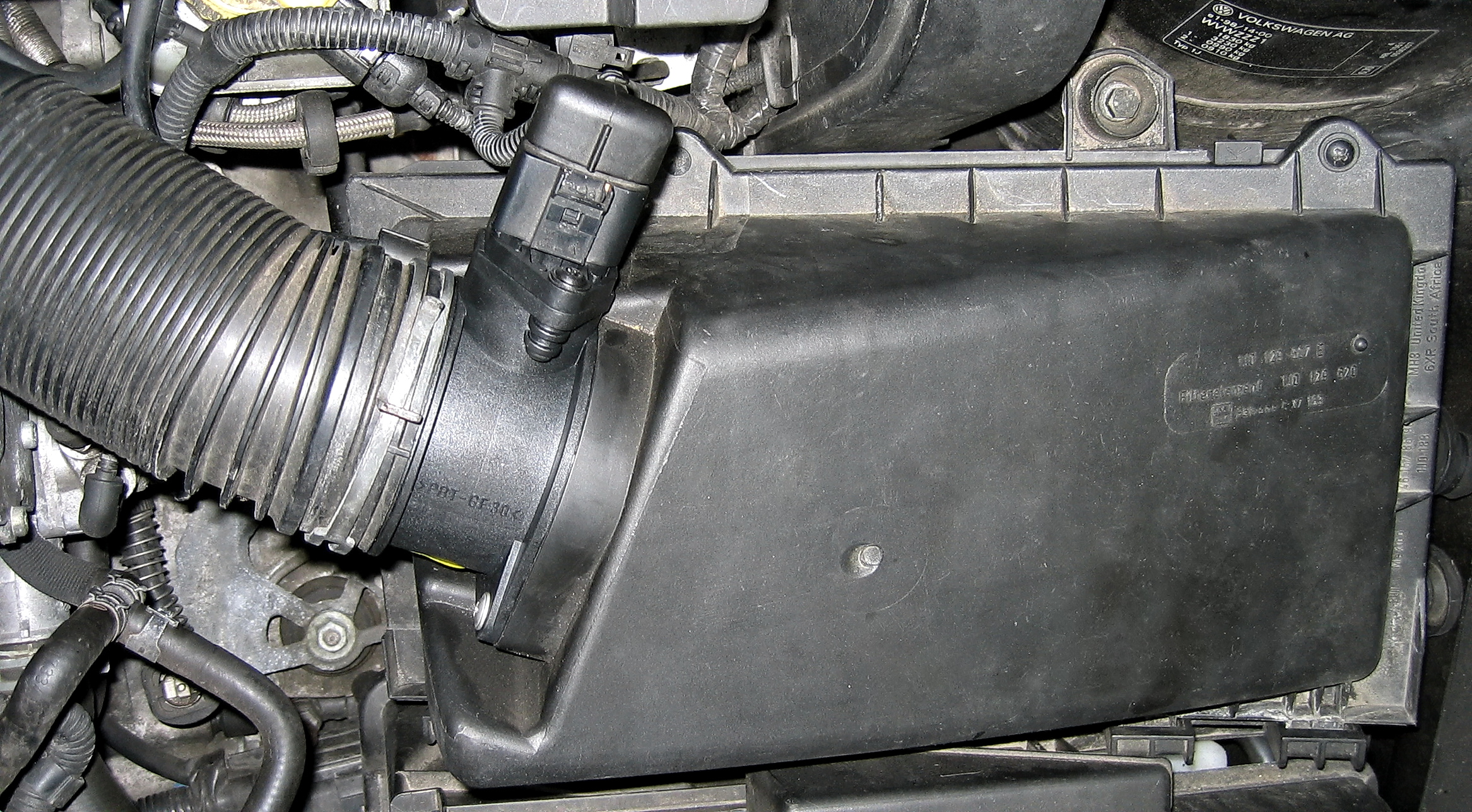
Air-mass meter and airbox on a Golf IV 1.9 TDI ARL, shown as an intake-location example. Some MAF assemblies contain an IAT sensor; this photograph alone does not establish the IAT arrangement of this vehicle. Photo: Johann H. Addicks via Wikimedia Commons, CC BY-SA 3.0; unchanged.
How many IAT sensors work
Many use a negative-temperature-coefficient (NTC) thermistor: resistance decreases as the sensing element warms. The ECU interprets the sensor and its input circuit using a temperature calibration. Other circuit designs exist, including sensors integrated into more complex assemblies. Identify the sensor type before testing, and use the exact wiring and temperature/resistance specifications for that vehicle.
Typical NTC trend: resistance falls as temperature rises. The curve is illustrative and gives no values for a particular sensor. Original Tuning Wiki illustration by OpenAI Codex, commissioned for use on Tuning Wiki. Technical basis: HELLA IAT sensor information.
A resistance reading changes with the temperature of the element, not just the surrounding workshop. An in-range result at one temperature does not prove correct response across the range or a sound circuit when the engine vibrates or heats up.
Common causes and fault codes
Open, short or intermittent wiring: damaged insulation, stretched wiring, loose terminals, corrosion or water and oil contamination can distort the signal.
Sensor or connector damage: a damaged sensing element, poor electrical contact or contamination may make a reading implausible or slow to respond.
Wrong sensor or calibration: a visually similar sensor may use a different temperature curve. On programmable ECUs, the selected sensor curve and input circuit must match the installation.
Real temperature or location effect: compressor heating, intercooler performance, airflow and heat soak can change the temperature at the sensing point.
Generic P0110–P0114 codes commonly refer to IAT circuit, range/performance, low, high and intermittent faults. P0095–P0099 commonly concern IAT sensor 2; P0127 indicates intake air temperature too high. Consult the complete manufacturer-specific definition and sensor location. A circuit high or low code refers to an electrical input, not automatically a high or low actual air temperature. See the HELLA OBD code list.
Practical diagnostic sequence
Record the fault. Save codes, freeze-frame data and the conditions in which the complaint occurs. Identify recent sensor, intake, intercooler or calibration work.
Identify the correct measurement. Find the sensor number, physical location, whether it is separate or integrated, and the matching live-data parameter. Note whether the engine has been running recently.
Compare after a cold soak. When the engine, intake and surroundings have had time to reach a similar temperature, compare IAT with a reliable ambient measurement and, where appropriate, coolant and other temperature readings. Different locations, sunlight and recent operation can still cause differences; use the manufacturer’s tolerance.
Inspect the installation. With the engine stopped, check the connector, terminals and harness for damage, moisture or oil, and check that the sensor and intake seals are installed correctly. Do not touch delicate sensing elements.
Check signal and circuit. Use the correct wiring diagram and manufacturer’s test method to measure specified reference, signal and ground. Compare the reading at the sensor and ECU where indicated. Repair wiring faults before condemning the sensor.
Test a confirmed thermistor if specified. Isolate the circuit as directed and measure resistance at a known, appropriate element temperature. Compare more than one temperature with the manufacturer’s curve if the procedure calls for it. Never use an ohmmeter on a powered circuit or unspecified pins of an integrated sensor.
Check response and real air temperature. Compare the ECU value with an independent suitable thermometer at the same location and under repeatable conditions. A surface infrared reading is not automatically the air temperature. Investigate sensor response, heat soak or the charge-air system as the evidence indicates.
Repair and verify. Fit the specified part and seal, reconnect the harness and repeat the original cold, hot or driving conditions safely. Clear codes at the appropriate stage and check for returning faults.
Keep hands and test leads clear of hot components, belts and fans. Do not open a hot or pressurised intake system, and avoid using an open flame or excessive heat to test the sensor. Follow the manufacturer’s isolation and testing instructions.
Hot readings, heat soak and intercooler checks
A sensor reports its own element temperature, influenced by the surrounding air, its mounting and airflow. After a hot stop, heat conducted from the manifold or sensor body can raise the indicated temperature; the response after restart depends on airflow and construction. That does not automatically mean the sensor or intercooler is faulty. Temperatures at the airbox and downstream of a compressor or intercooler are different measurements and should not be expected to match while operating.
If downstream temperature remains unexpectedly high under comparable conditions, investigate real charge-air temperature and the cooling system fitted to that vehicle: airflow through the intercooler, obstruction or damage and, for a liquid-cooled system, its relevant cooling circuit. Use vehicle-specific test conditions and independent measurements before deciding on a repair. See intake air temperature sensors and heat soak.
Reading electrical faults without guessing
For a common ECU pull-up and NTC circuit, an open circuit can produce a high signal voltage interpreted as a very cold reading, while a short to sensor ground can produce a low voltage interpreted as very hot. Other circuits and fallback strategies differ, so confirm the wiring and expected response. A scan tool may show a substituted value, and a plausible value does not prove that the sensor is accurate.
When a combined MAF/IAT or pressure/IAT assembly is fitted, test the specified temperature circuit without assuming the airflow or pressure circuit shares its pins or has failed. Avoid improvised jumper tests or introducing a fixed resistor unless the manufacturer’s diagnostic procedure specifically calls for it.
Replacement and final checks
Use the correct sensor or integrated assembly and seal, and fit it at the specified location. Clean only when the component maker approves the method; solvents or contact with the element may damage it. On aftermarket management, confirm the correct sensor calibration and input configuration rather than copying an unrelated resistance table. Verify the reading against a suitable reference and repeat the original complaint; investigate high real charge temperature separately from a sensor fault.
Related diagnostic guides
AdBlue and SCR system faults — fluid supply, dosing and SCR efficiency checks.NOx sensor faults — NOx measurement, wiring and SCR checks.DPF differential pressure sensor faults — pressure hoses, sensor readings and filter restriction.Exhaust gas temperature sensor faults — exhaust temperature, wiring and regeneration checks.Knock sensor faultsAccelerator pedal position sensor faultsThrottle position sensor faultsCamshaft position sensor faultsCrankshaft position sensor faultsCoolant temperature sensor faultsOxygen sensor faultsMAP sensor faultsMAF sensor faultsFuel pressure sensor faultsFuel pump faultsInjector faultsDPF faultsEGR faultsTurbo diagnosticsBoost leaksIntake air temperature sensors and heat soakKnock sensor faultsAccelerator pedal position sensor faultsThrottle position sensor faultsCamshaft position sensor faultsCrankshaft position sensor faultsCoolant temperature sensor faultsOxygen sensor faultsMAP sensor faultsMAF sensor faultsFuel pressure sensor faultsFuel pump faultsInjector faultsDPF faultsEGR faultsTurbo diagnosticsBoost leaksIntake air temperature sensors and heat soak
Rendered revisions
Open each version to inspect formatting, tables and photographs.
Revision 1: Common intake air temperature sensor faults: symptoms, checks and diagnosis
The intake air temperature sensor (IAT) reports the temperature at its position in the intake system. The engine control unit (ECU) uses this information, alongside other measurements, for functions such as air-charge estimation, fuelling and engine protection. An implausible reading may come from the sensor, its wiring or calibration; a high reading may also reflect genuinely hot air or heat absorbed from the installation.
Possible temperature measurement positions in a simplified turbocharged intake. This is not a layout for a specific vehicle; not every engine has both sensors. Original Tuning Wiki illustration by OpenAI Codex, commissioned for use on Tuning Wiki. Technical basis: Bosch integrated intake pressure and temperature sensor.
Symptoms and first checks
Observation
What to investigate
Engine warning light or IAT code
Record the full code, sensor number and freeze-frame data; check the correct circuit, connector, location and temperature reading.
Poor cold starting, uneven running or hesitation
Compare temperatures after a cold soak and check the sensor circuit. Fuel, ignition, coolant temperature and air leaks can cause similar symptoms.
Reduced power or poor economy
Check whether the reported temperature is plausible and whether a protective strategy is active. Airflow, boost, fuel delivery and exhaust restrictions are other possibilities.
Very hot or cold value immediately after key-on
Inspect the circuit and identify the ECU’s fallback value. An extreme number can indicate an electrical fault but is not proof of a failed sensor.
High reading after a hot restart or under boost
Consider sensor location, hot-soak conditions and actual charge-air temperature. Compare using an independent measurement before replacing parts.
Symptoms and ECU fallback strategies vary. HELLA’s IAT guidance describes temperature-dependent resistance and electrical checks. A temperature reading alone cannot establish the cause of a running fault.
Where is the sensor?
An IAT sensor can be a separate component in an intake duct or manifold, or it can share a housing with another sensor. Some mass-airflow meters incorporate intake temperature measurement; some manifold or boost-pressure sensors incorporate an IAT element, often called a combined pressure/temperature or TMAP sensor. More than one temperature sensor may be fitted. The diagnostic code and wiring diagram identify the relevant sensor, not the appearance of the housing alone. HELLA’s combined sensor information and Bosch’s pressure/temperature description provide examples.
Air-mass meter and airbox on a Golf IV 1.9 TDI ARL, shown as an intake-location example. Some MAF assemblies contain an IAT sensor; this photograph alone does not establish the IAT arrangement of this vehicle. Photo: Johann H. Addicks via Wikimedia Commons, CC BY-SA 3.0; unchanged.
How many IAT sensors work
Many use a negative-temperature-coefficient (NTC) thermistor: resistance decreases as the sensing element warms. The ECU interprets the sensor and its input circuit using a temperature calibration. Other circuit designs exist, including sensors integrated into more complex assemblies. Identify the sensor type before testing, and use the exact wiring and temperature/resistance specifications for that vehicle.
Typical NTC trend: resistance falls as temperature rises. The curve is illustrative and gives no values for a particular sensor. Original Tuning Wiki illustration by OpenAI Codex, commissioned for use on Tuning Wiki. Technical basis: HELLA IAT sensor information.
A resistance reading changes with the temperature of the element, not just the surrounding workshop. An in-range result at one temperature does not prove correct response across the range or a sound circuit when the engine vibrates or heats up.
Common causes and fault codes
Open, short or intermittent wiring: damaged insulation, stretched wiring, loose terminals, corrosion or water and oil contamination can distort the signal.
Sensor or connector damage: a damaged sensing element, poor electrical contact or contamination may make a reading implausible or slow to respond.
Wrong sensor or calibration: a visually similar sensor may use a different temperature curve. On programmable ECUs, the selected sensor curve and input circuit must match the installation.
Real temperature or location effect: compressor heating, intercooler performance, airflow and heat soak can change the temperature at the sensing point.
Generic P0110–P0114 codes commonly refer to IAT circuit, range/performance, low, high and intermittent faults. P0095–P0099 commonly concern IAT sensor 2; P0127 indicates intake air temperature too high. Consult the complete manufacturer-specific definition and sensor location. A circuit high or low code refers to an electrical input, not automatically a high or low actual air temperature. See the HELLA OBD code list.
Practical diagnostic sequence
Record the fault. Save codes, freeze-frame data and the conditions in which the complaint occurs. Identify recent sensor, intake, intercooler or calibration work.
Identify the correct measurement. Find the sensor number, physical location, whether it is separate or integrated, and the matching live-data parameter. Note whether the engine has been running recently.
Compare after a cold soak. When the engine, intake and surroundings have had time to reach a similar temperature, compare IAT with a reliable ambient measurement and, where appropriate, coolant and other temperature readings. Different locations, sunlight and recent operation can still cause differences; use the manufacturer’s tolerance.
Inspect the installation. With the engine stopped, check the connector, terminals and harness for damage, moisture or oil, and check that the sensor and intake seals are installed correctly. Do not touch delicate sensing elements.
Check signal and circuit. Use the correct wiring diagram and manufacturer’s test method to measure specified reference, signal and ground. Compare the reading at the sensor and ECU where indicated. Repair wiring faults before condemning the sensor.
Test a confirmed thermistor if specified. Isolate the circuit as directed and measure resistance at a known, appropriate element temperature. Compare more than one temperature with the manufacturer’s curve if the procedure calls for it. Never use an ohmmeter on a powered circuit or unspecified pins of an integrated sensor.
Check response and real air temperature. Compare the ECU value with an independent suitable thermometer at the same location and under repeatable conditions. A surface infrared reading is not automatically the air temperature. Investigate sensor response, heat soak or the charge-air system as the evidence indicates.
Repair and verify. Fit the specified part and seal, reconnect the harness and repeat the original cold, hot or driving conditions safely. Clear codes at the appropriate stage and check for returning faults.
Keep hands and test leads clear of hot components, belts and fans. Do not open a hot or pressurised intake system, and avoid using an open flame or excessive heat to test the sensor. Follow the manufacturer’s isolation and testing instructions.
Hot readings, heat soak and intercooler checks
A sensor reports its own element temperature, influenced by the surrounding air, its mounting and airflow. After a hot stop, heat conducted from the manifold or sensor body can raise the indicated temperature; the response after restart depends on airflow and construction. That does not automatically mean the sensor or intercooler is faulty. Temperatures at the airbox and downstream of a compressor or intercooler are different measurements and should not be expected to match while operating.
If downstream temperature remains unexpectedly high under comparable conditions, investigate real charge-air temperature and the cooling system fitted to that vehicle: airflow through the intercooler, obstruction or damage and, for a liquid-cooled system, its relevant cooling circuit. Use vehicle-specific test conditions and independent measurements before deciding on a repair. See intake air temperature sensors and heat soak.
Reading electrical faults without guessing
For a common ECU pull-up and NTC circuit, an open circuit can produce a high signal voltage interpreted as a very cold reading, while a short to sensor ground can produce a low voltage interpreted as very hot. Other circuits and fallback strategies differ, so confirm the wiring and expected response. A scan tool may show a substituted value, and a plausible value does not prove that the sensor is accurate.
When a combined MAF/IAT or pressure/IAT assembly is fitted, test the specified temperature circuit without assuming the airflow or pressure circuit shares its pins or has failed. Avoid improvised jumper tests or introducing a fixed resistor unless the manufacturer’s diagnostic procedure specifically calls for it.
Replacement and final checks
Use the correct sensor or integrated assembly and seal, and fit it at the specified location. Clean only when the component maker approves the method; solvents or contact with the element may damage it. On aftermarket management, confirm the correct sensor calibration and input configuration rather than copying an unrelated resistance table. Verify the reading against a suitable reference and repeat the original complaint; investigate high real charge temperature separately from a sensor fault.
Revision 8: Common intake air temperature sensor faults: symptoms, checks and diagnosis
The intake air temperature sensor (IAT) reports the temperature at its position in the intake system. The engine control unit (ECU) uses this information, alongside other measurements, for functions such as air-charge estimation, fuelling and engine protection. An implausible reading may come from the sensor, its wiring or calibration; a high reading may also reflect genuinely hot air or heat absorbed from the installation.
Possible temperature measurement positions in a simplified turbocharged intake. This is not a layout for a specific vehicle; not every engine has both sensors. Original Tuning Wiki illustration by OpenAI Codex, commissioned for use on Tuning Wiki. Technical basis: Bosch integrated intake pressure and temperature sensor.
Symptoms and first checks
Observation
What to investigate
Engine warning light or IAT code
Record the full code, sensor number and freeze-frame data; check the correct circuit, connector, location and temperature reading.
Poor cold starting, uneven running or hesitation
Compare temperatures after a cold soak and check the sensor circuit. Fuel, ignition, coolant temperature and air leaks can cause similar symptoms.
Reduced power or poor economy
Check whether the reported temperature is plausible and whether a protective strategy is active. Airflow, boost, fuel delivery and exhaust restrictions are other possibilities.
Very hot or cold value immediately after key-on
Inspect the circuit and identify the ECU’s fallback value. An extreme number can indicate an electrical fault but is not proof of a failed sensor.
High reading after a hot restart or under boost
Consider sensor location, hot-soak conditions and actual charge-air temperature. Compare using an independent measurement before replacing parts.
Symptoms and ECU fallback strategies vary. HELLA’s IAT guidance describes temperature-dependent resistance and electrical checks. A temperature reading alone cannot establish the cause of a running fault.
Where is the sensor?
An IAT sensor can be a separate component in an intake duct or manifold, or it can share a housing with another sensor. Some mass-airflow meters incorporate intake temperature measurement; some manifold or boost-pressure sensors incorporate an IAT element, often called a combined pressure/temperature or TMAP sensor. More than one temperature sensor may be fitted. The diagnostic code and wiring diagram identify the relevant sensor, not the appearance of the housing alone. HELLA’s combined sensor information and Bosch’s pressure/temperature description provide examples.
Air-mass meter and airbox on a Golf IV 1.9 TDI ARL, shown as an intake-location example. Some MAF assemblies contain an IAT sensor; this photograph alone does not establish the IAT arrangement of this vehicle. Photo: Johann H. Addicks via Wikimedia Commons, CC BY-SA 3.0; unchanged.
How many IAT sensors work
Many use a negative-temperature-coefficient (NTC) thermistor: resistance decreases as the sensing element warms. The ECU interprets the sensor and its input circuit using a temperature calibration. Other circuit designs exist, including sensors integrated into more complex assemblies. Identify the sensor type before testing, and use the exact wiring and temperature/resistance specifications for that vehicle.
Typical NTC trend: resistance falls as temperature rises. The curve is illustrative and gives no values for a particular sensor. Original Tuning Wiki illustration by OpenAI Codex, commissioned for use on Tuning Wiki. Technical basis: HELLA IAT sensor information.
A resistance reading changes with the temperature of the element, not just the surrounding workshop. An in-range result at one temperature does not prove correct response across the range or a sound circuit when the engine vibrates or heats up.
Common causes and fault codes
Open, short or intermittent wiring: damaged insulation, stretched wiring, loose terminals, corrosion or water and oil contamination can distort the signal.
Sensor or connector damage: a damaged sensing element, poor electrical contact or contamination may make a reading implausible or slow to respond.
Wrong sensor or calibration: a visually similar sensor may use a different temperature curve. On programmable ECUs, the selected sensor curve and input circuit must match the installation.
Real temperature or location effect: compressor heating, intercooler performance, airflow and heat soak can change the temperature at the sensing point.
Generic P0110–P0114 codes commonly refer to IAT circuit, range/performance, low, high and intermittent faults. P0095–P0099 commonly concern IAT sensor 2; P0127 indicates intake air temperature too high. Consult the complete manufacturer-specific definition and sensor location. A circuit high or low code refers to an electrical input, not automatically a high or low actual air temperature. See the HELLA OBD code list.
Practical diagnostic sequence
Record the fault. Save codes, freeze-frame data and the conditions in which the complaint occurs. Identify recent sensor, intake, intercooler or calibration work.
Identify the correct measurement. Find the sensor number, physical location, whether it is separate or integrated, and the matching live-data parameter. Note whether the engine has been running recently.
Compare after a cold soak. When the engine, intake and surroundings have had time to reach a similar temperature, compare IAT with a reliable ambient measurement and, where appropriate, coolant and other temperature readings. Different locations, sunlight and recent operation can still cause differences; use the manufacturer’s tolerance.
Inspect the installation. With the engine stopped, check the connector, terminals and harness for damage, moisture or oil, and check that the sensor and intake seals are installed correctly. Do not touch delicate sensing elements.
Check signal and circuit. Use the correct wiring diagram and manufacturer’s test method to measure specified reference, signal and ground. Compare the reading at the sensor and ECU where indicated. Repair wiring faults before condemning the sensor.
Test a confirmed thermistor if specified. Isolate the circuit as directed and measure resistance at a known, appropriate element temperature. Compare more than one temperature with the manufacturer’s curve if the procedure calls for it. Never use an ohmmeter on a powered circuit or unspecified pins of an integrated sensor.
Check response and real air temperature. Compare the ECU value with an independent suitable thermometer at the same location and under repeatable conditions. A surface infrared reading is not automatically the air temperature. Investigate sensor response, heat soak or the charge-air system as the evidence indicates.
Repair and verify. Fit the specified part and seal, reconnect the harness and repeat the original cold, hot or driving conditions safely. Clear codes at the appropriate stage and check for returning faults.
Keep hands and test leads clear of hot components, belts and fans. Do not open a hot or pressurised intake system, and avoid using an open flame or excessive heat to test the sensor. Follow the manufacturer’s isolation and testing instructions.
Hot readings, heat soak and intercooler checks
A sensor reports its own element temperature, influenced by the surrounding air, its mounting and airflow. After a hot stop, heat conducted from the manifold or sensor body can raise the indicated temperature; the response after restart depends on airflow and construction. That does not automatically mean the sensor or intercooler is faulty. Temperatures at the airbox and downstream of a compressor or intercooler are different measurements and should not be expected to match while operating.
If downstream temperature remains unexpectedly high under comparable conditions, investigate real charge-air temperature and the cooling system fitted to that vehicle: airflow through the intercooler, obstruction or damage and, for a liquid-cooled system, its relevant cooling circuit. Use vehicle-specific test conditions and independent measurements before deciding on a repair. See intake air temperature sensors and heat soak.
Reading electrical faults without guessing
For a common ECU pull-up and NTC circuit, an open circuit can produce a high signal voltage interpreted as a very cold reading, while a short to sensor ground can produce a low voltage interpreted as very hot. Other circuits and fallback strategies differ, so confirm the wiring and expected response. A scan tool may show a substituted value, and a plausible value does not prove that the sensor is accurate.
When a combined MAF/IAT or pressure/IAT assembly is fitted, test the specified temperature circuit without assuming the airflow or pressure circuit shares its pins or has failed. Avoid improvised jumper tests or introducing a fixed resistor unless the manufacturer’s diagnostic procedure specifically calls for it.
Replacement and final checks
Use the correct sensor or integrated assembly and seal, and fit it at the specified location. Clean only when the component maker approves the method; solvents or contact with the element may damage it. On aftermarket management, confirm the correct sensor calibration and input configuration rather than copying an unrelated resistance table. Verify the reading against a suitable reference and repeat the original complaint; investigate high real charge temperature separately from a sensor fault.