A knock sensor listens for vibration transmitted through the engine. On many petrol engines the engine control unit (ECU) analyses that signal to help detect knocking combustion and adjust ignition timing. A sensor circuit fault, an incorrect mounting, mechanical noise and genuine combustion knock need different repairs: a fault code or a timing correction alone does not identify the cause.

Symptoms and first checks
| Observation | What to investigate |
|---|---|
| Engine warning lamp or knock-sensor code | Record the full code and freeze-frame information. Identify the correct sensor, circuit, connector and mounting; follow the manufacturer's test plan. |
| Reduced power or increased fuel consumption | A control strategy may change timing when a fault is detected. Check codes and data, but also investigate air, fuel, ignition and boost faults. |
| Pinking or pinging under load | Reduce load and investigate fuel, temperature, ignition and mixture. Do not continue loading the engine to reproduce potentially damaging knock. |
| Timing correction or knock-retard reading | Compare readings with the manufacturer's data and operating conditions. The ECU's interpretation may reflect combustion, mechanical noise, calibration or a sensing problem. |
| Fault after engine or sensor work | Inspect the correct sensor, mounting position and surface, fastener, specified torque, connector and harness routing. |
HELLA lists a warning lamp, reduced power and increased fuel consumption among possible effects of a knock sensor fault. Symptoms and ECU fallback strategies vary by vehicle; the engine may show no obvious symptom beyond a stored code.
What the sensor does
Many knock sensors contain a piezoelectric element that generates a voltage when engine vibration stresses it. The ECU processes the signal in the context of engine operation; on applicable spark-ignition systems it can reduce knock tendency by retarding ignition timing. Different sensors can be tuned to a narrower frequency range or respond across a wider range. Their wiring, shielding and ECU circuitry differ. Pico's knock-sensor test explains the sensor types and the role of ignition control.
Do not assume that every diesel uses a separate sensor for spark-knock control, or apply petrol ignition-retard interpretations to a diesel. Some diesel systems use engine vibration or combustion-related feedback for their own control strategies; follow the relevant vehicle documentation.
Sensor fault, mechanical noise or real knock?
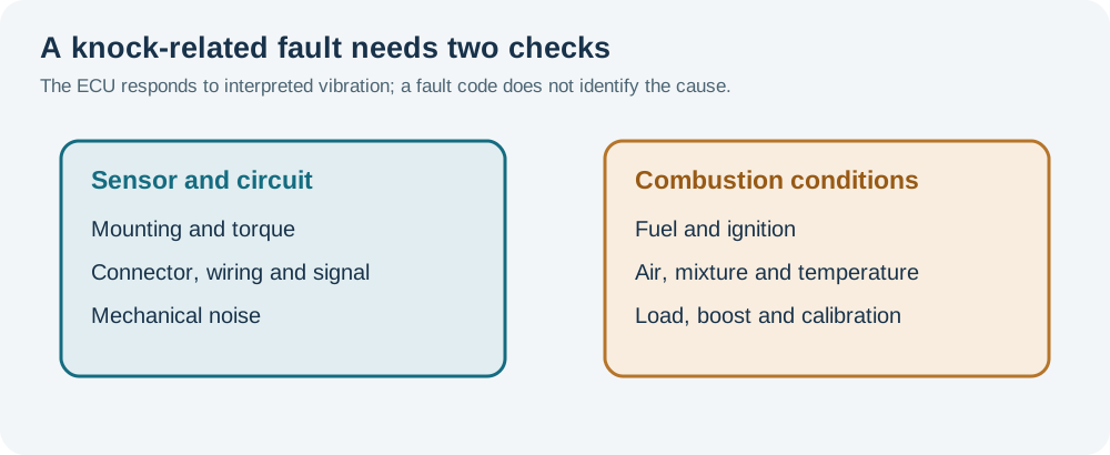
- Sensor or circuit: damaged housing, corrosion, open or shorted wiring, incorrect sensor or connector problems can prevent the ECU receiving the expected signal.
- Mounting: an unsuitable contact surface, incorrect fastener or tightening torque, or a sensor installed in the wrong place can affect vibration transfer.
- Other mechanical noise: loose components or abnormal engine mechanical noise can add vibration. A large signal is not automatically combustion knock.
- Combustion knock: unsuitable fuel, excessive intake or engine temperature, an overly lean mixture, excessive ignition advance, high load or boost and engine deposits are possible contributors. Determine which applies to the vehicle rather than assuming one cause.
In a spark-ignition engine, knock involves abnormal combustion after spark initiation and can create damaging pressure oscillations. It is not the same as pre-ignition, where combustion begins before the intended spark. Both require attention. See Pico's explanation of knock and the wiki guide to fuel octane.
Common fault codes
P0325–P0329 commonly describe knock sensor 1 circuit, range/performance, low, high or intermittent problems; P0330–P0334 cover corresponding sensor 2 codes. P0324 concerns knock control system performance. Bank and sensor numbering and the detailed test conditions depend on the manufacturer. Read the complete vehicle-specific definition before deciding which sensor or connector to test; see the HELLA OBD code list.
Practical diagnostic sequence
- Record the complaint. Save all codes and freeze-frame data. Note operating temperature, load, fuel grade, recent repairs, engine modifications and whether the driver heard a noise.
- Make the engine safe. If there is persistent pinging, severe mechanical noise or suspected overheating, stop the test and investigate before further load. Keep hands and leads clear of hot or moving components.
- Identify the system. Use the vehicle information to identify the exact sensor, location, wiring, shielding, fastener, torque and test procedure. Do not assume sensor 1 is always the front sensor or a particular bank.
- Inspect the installation. With the engine stopped and cool enough to work on, check accessible connectors, harness routing, heat damage, corrosion and mounting condition. Follow the manufacturer’s instructions before disturbing the sensor or its fastener.
- Check the circuit. Use the specified ECU and sensor connector isolation procedure for continuity, short-circuit and shield checks. A shield may be grounded by design, and a sensor can contain an internal diagnostic resistor. Do not apply a generic resistance value or insulation test to an unidentified circuit.
- Inspect the signal when indicated. Use the manufacturer’s specified test method and scope setup, including a suitable attenuated probe and correct reference or isolation. Compare at the sensor and ECU if the procedure calls for it. A visible response confirms only that a signal is present under that test; it does not establish accurate knock detection throughout the operating range.
- Assess the engine. Check for relevant mechanical noises and use the manufacturer’s procedure to investigate fuel, ignition, temperatures, mixture and boost where real knock is suspected. Record the conditions without deliberately inducing knock.
- Repair and verify. Correct the cause, fit the correct parts and perform any specified reset or adaptation. Clear codes when appropriate and confirm the original complaint under safe operating conditions.
Some guided tests use a light tap on the engine block to check for a sensor response. Only use that technique when the manufacturer’s procedure permits it, with appropriate safety and scope setup; a tap does not reproduce combustion knock or prove the ECU's calibration. Never strike the sensor itself or run an engine under damaging knock as a test.
Interpreting live data and waveforms
Knock-related live data may show detected activity, ignition correction or learned adaptations rather than a raw sensor voltage. Parameter names, signs, units and update rates vary. A non-zero correction can be part of normal control; a high or persistent correction is a reason to investigate conditions and compare with the manufacturer’s limits. An apparently quiet reading is not proof that the sensor is correctly coupled or that the engine cannot knock.
A sensor waveform contains normal engine vibration as well as other signals. Amplitude changes with engine speed, load, mounting and sensor design, so there is no universal voltage threshold for diagnosing knock. ECU filtering and cylinder timing matter. Compare the correct circuit and operating conditions with a suitable known-good reference; a disconnected or shorted circuit, loose mounting and genuine knock can produce very different findings.
Replacement and verification
Use the exact specified sensor, mounting position, fastener and torque. Prepare the mating surface as the manufacturer directs; do not add washers, sealant, thread treatment or relocate the sensor unless specified. Piezoelectric elements can be damaged by improper handling or overtightening. Restore wiring and shielding as designed, and carry out adaptations only if required.
After repair, check fault memory and relevant data, confirm the complaint is resolved and investigate any persistent abnormal noise or knock. If the car is modified, review fuel, boost and calibration with a suitably qualified specialist; do not disable knock protection to hide a fault.
Related diagnostic guides
- AdBlue and SCR system faults — fluid supply, dosing and SCR efficiency checks.
- NOx sensor faults — NOx measurement, wiring and SCR checks.
- DPF differential pressure sensor faults — pressure hoses, sensor readings and filter restriction.
- Exhaust gas temperature sensor faults — exhaust temperature, wiring and regeneration checks.
- Intake air temperature sensor faults — air temperature, wiring and heat-soak checks.
- Accelerator pedal position sensor faults
- Throttle position sensor faults
- Camshaft position sensor faults
- Crankshaft position sensor faults
- Coolant temperature sensor faults
- Oxygen sensor faults
- MAP sensor faults
- MAF sensor faults
- Fuel pressure sensor faults
- Fuel pump faults
- Injector faults
- DPF faults
- EGR faults
- Turbo diagnostics
- Boost leaks