A NOx sensor monitors nitrogen oxides in the exhaust. Depending on the vehicle, the engine or exhaust control system uses its reading to manage and check emissions control, including selective catalytic reduction (SCR) with AdBlue or diesel exhaust fluid. A NOx-related warning can be caused by the sensor assembly, its supply or communications, exhaust leaks, dosing faults or the catalyst. Test the system before replacing the sensor.

Symptoms and first checks
| Observation | What to investigate |
|---|---|
| Engine or emissions warning light | Save all fault codes and freeze-frame information from the relevant engine and aftertreatment controllers. Identify the exact sensor and fault type. |
| AdBlue or SCR warning, or restart countdown | Check the displayed instructions and the complete SCR system fault record. A countdown may have several causes; do not assume a top-up or sensor replacement will clear it. |
| Reduced performance or restricted operation | Check the manufacturer's fault strategy and investigate the sensor, power, communication and aftertreatment system as indicated. |
| Missing, fixed or implausible NOx value | Check sensor readiness, heater, wiring, supply and network communication. Compare values only in the operating conditions specified for the vehicle. |
| Fault after exhaust or sensor work | Check correct upstream/downstream part, connector, harness routing, exhaust sealing and any specified initialisation. |
HELLA lists warning lights, SCR faults and reduced performance among possible symptoms. Warning and restart strategies vary by vehicle. If a countdown is displayed, follow the vehicle instructions and arrange diagnosis promptly.
What a NOx sensor does
Many assemblies consist of an exhaust probe connected to a dedicated sensor control module, which processes the measurement and communicates with the engine or aftertreatment controller. The probe has a heater and must reach its operating conditions before readings can be interpreted as specified. Depending on the vehicle, sensors may be fitted upstream and downstream of the SCR catalyst. Other engine and aftertreatment layouts exist, including petrol applications.
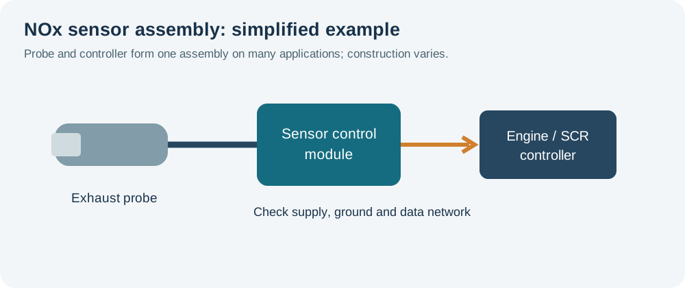
A NOx sensor is different from an oxygen sensor, exhaust gas temperature sensor or DPF differential pressure sensor. Do not test its internal probe as if it were a simple analogue oxygen or temperature sensor. Consult the exact system wiring, connector identification and manufacturer test procedure.
Common causes of NOx-related faults
- Power, ground or wiring: damaged insulation, corrosion, water ingress, loose terminals or a broken conductor can interrupt sensor supply or communication.
- Sensor heater or module: a heater, sensing element or control module can fail or be slow to become ready. Ageing may also cause an inaccurate reading despite apparently normal communications.
- Exhaust damage or leaks: leaks and damaged components can alter exhaust conditions and affect measurement or SCR assessment.
- SCR fluid and dosing: incorrect or contaminated fluid, a dosing, supply or control fault, or deposits can prevent the system operating correctly.
- Other engine or aftertreatment faults: EGR, fuelling, temperature, catalyst or exhaust-system problems can change NOx levels or SCR performance without a failed sensor.
- Installation and calibration: the wrong upstream/downstream part, incorrect routing or a missed required initialisation can cause recurring faults.
HELLA discusses sensor ageing, soot, wiring damage and SCR-related influences in its NOx diagnostic guidance. These are possibilities to investigate, not a checklist of parts to replace.
Fault codes and what they mean
Generic P2200–P2204 codes commonly describe a bank 1 NOx sensor circuit or range/performance fault; P2205–P2207 commonly concern its heater control circuit. Other codes can concern another bank, sensor, communication, reductant dosing or SCR efficiency. Bank and sensor numbering, extended codes and test conditions vary by manufacturer. A communication fault does not automatically condemn the probe, and an SCR efficiency code does not by itself prove the downstream NOx sensor has failed. Consult the exact vehicle fault tree and HELLA OBD code list.
Practical diagnostic sequence
- Record the complaint. Save the complete fault memory and freeze-frame data from the engine and relevant emissions controllers. Record warnings, countdown information, operating conditions and recent repairs before clearing codes.
- Identify the correct assembly. Use the vehicle-specific layout and part information to locate the indicated sensor, its probe, module, connector and upstream or downstream position. Do not assume sensor numbering is universal.
- Inspect safely. Let the exhaust cool, secure the vehicle and inspect accessible probe wiring, module mountings and connectors for chafing, heat, corrosion, moisture or impact damage. Look for exhaust leaks and relevant SCR deposits without disturbing hot parts.
- Check supply and ground. Use the correct wiring diagram and measure the specified power and ground under the manufacturer’s stated conditions. Check fuses, connectors and voltage drop where specified before condemning the module.
- Check communication. If the module communicates over a data network, follow the vehicle’s network diagnostic procedure for missing messages, power-down conditions and wiring faults. Do not assume a CAN fault belongs to the NOx sensor alone; other modules or the network may be affected.
- Review readiness and live data. Under the specified operating conditions, examine sensor readiness, relevant NOx and temperature parameters and SCR status. Allow for warm-up, filtering and the applicable driving cycle. A fixed or missing reading is a clue requiring the appropriate circuit and system tests.
- Assess SCR and engine conditions. If the sensor communicates but readings or conversion are implausible, follow the manufacturer’s procedure for exhaust leaks, reductant quality and delivery, dosing, temperature, EGR and catalyst efficiency. Do not diagnose a catalyst or sensor solely from two instantaneous ppm values.
- Repair and verify. Correct the demonstrated cause, install the specified complete assembly where required and perform any prescribed coding, initialisation or adaptation. Repeat the manufacturer’s verification drive or monitor test when safe, then check fault memory and warning status.
Exhaust components can remain extremely hot after driving or regeneration. Secure the vehicle, let components cool and follow the vehicle maker’s workshop instructions. Use a suitable diagnostic interface and avoid direct probing of unidentified probe wires, applying external power to the sensor, or disconnecting network components in an unspecified manner.
Reading upstream and downstream NOx values
Upstream and downstream sensors, where fitted, monitor different points. Their readings change with engine load, exhaust temperature, SCR dosing and operating state; the downstream value is not expected to be a fixed percentage of the upstream value at all times. Sensor warm-up and communication status matter. Compare data under the vehicle manufacturer’s defined conditions, including temperatures and diagnostic readiness.
A plausible-looking value alone does not prove a sensor is accurate, and an implausible value may reflect exhaust conditions or a sensor fault. The controller’s SCR efficiency assessment uses more information than a single snapshot. An approved diagnostic test or suitable emissions measurement may be needed to distinguish sensor drift from dosing or catalyst problems.
AdBlue, warnings and related faults
Use the vehicle-specified reductant and handling procedure. Check level, quality, leaks, dosing and system faults as directed; adding fluid does not repair an electrical or efficiency fault. Do not erase faults repeatedly or disable emissions controls to clear a warning. A restart restriction or countdown may remain until the repair and required verification are completed.
Exhaust temperature and DPF faults can affect aftertreatment operation, but a DPF differential pressure sensor measures pressure rather than NOx. See DPF differential pressure sensor faults and exhaust gas temperature sensor faults.
Replacement and verification
Use the exact assembly and installation position specified for the vehicle. Many sensors are supplied as a matched probe, lead and control module; replace or repair only as the manufacturer permits. Protect the probe and cable, use the specified torque and thread treatment, and route wiring away from heat and moving parts. Do not add anti-seize or other compound unless the instructions specifically require it.
Some vehicles require coding, initialisation or adaptation after installation; others use a different procedure. Confirm the module communicates, the sensor becomes ready and readings are plausible under the prescribed conditions. Complete the required monitor or road test and confirm the warning and relevant fault codes are resolved.
Related diagnostic guides
- AdBlue and SCR system faults — fluid supply, dosing and SCR efficiency checks.
- DPF differential pressure sensor faults
- Exhaust gas temperature sensor faults
- Intake air temperature sensor faults
- Knock sensor faults
- Accelerator pedal position sensor faults
- Throttle position sensor faults
- Camshaft position sensor faults
- Crankshaft position sensor faults
- Coolant temperature sensor faults
- Oxygen sensor faults
- MAP sensor faults
- MAF sensor faults
- Fuel pressure sensor faults
- Fuel pump faults
- Injector faults
- DPF faults
- EGR faults
- Turbo diagnostics
- Boost leaks
- Intake air temperature sensors and heat soak