A mass air flow (MAF) sensor reports the amount of intake air entering the engine. Poor acceleration, rough running, smoke or an air-mass fault code can result from the sensor, but also from leaks, restrictions, wiring faults or the engine's control strategy. Test the complete air path before replacing the meter.

Air-metering and oxygen-sensor faults can produce similar mixture symptoms. See common oxygen sensor faults.
A coolant-temperature fault can also affect starting and drivability. See common coolant temperature sensor faults.
An intermittent crankshaft signal can also cause stalling or poor running. See common crankshaft position sensor faults.
Symptoms and first checks
| Observation | What to investigate |
|---|---|
| Hesitation, weak acceleration or reduced power | Log air mass and related load signals; check the air filter, intake and charge path, EGR, boost control and fuel supply. |
| Rough idle or stalling | Check air leaks, sensor wiring, fuelling, ignition where applicable and engine mechanical condition. |
| Warning light or P0100–P0104 | Identify the exact code and test the sensor circuit, air path and plausibility under the fault conditions. |
| Incorrect mixture or fuel trims on a petrol engine | Check unmetered air, fuel delivery, exhaust leaks and oxygen-sensor data as well as MAF plausibility. |
| Diesel smoke or an EGR flow fault | Investigate actual air supply, EGR operation, boost leaks, injectors and the sensor; smoke alone cannot identify the cause. |
Symptoms depend on the engine and strategy. A sensor can drift without an explicit sensor code. Bosch's fault-diagnosis guidance lists wiring, air leaks and contamination as possible causes of an apparently incorrect air-mass signal.
Where the MAF fits and what it measures
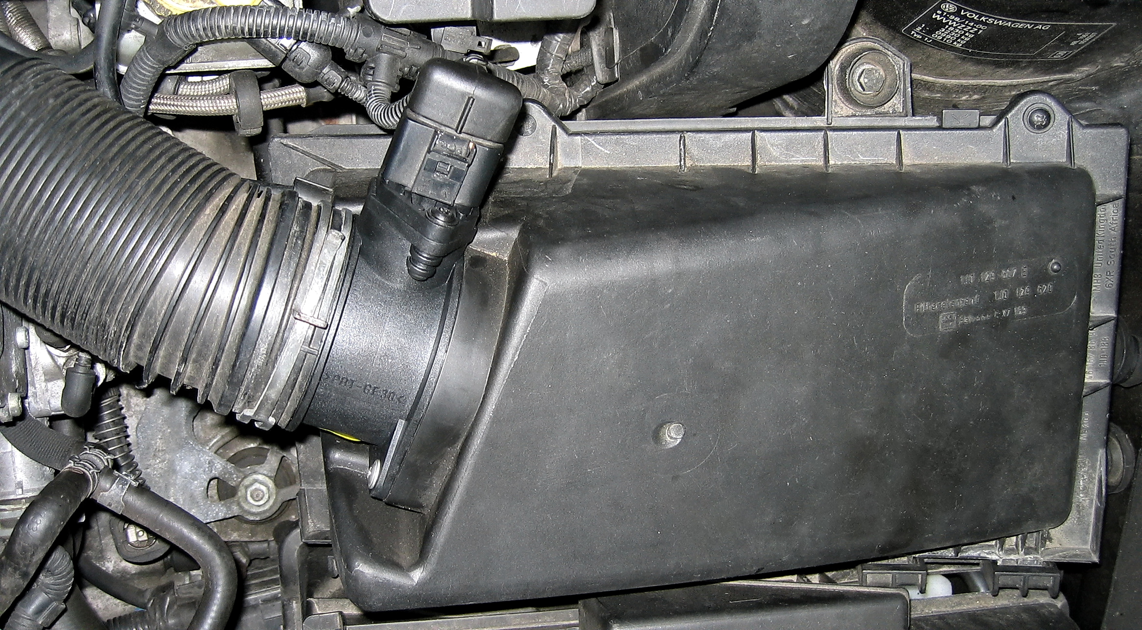

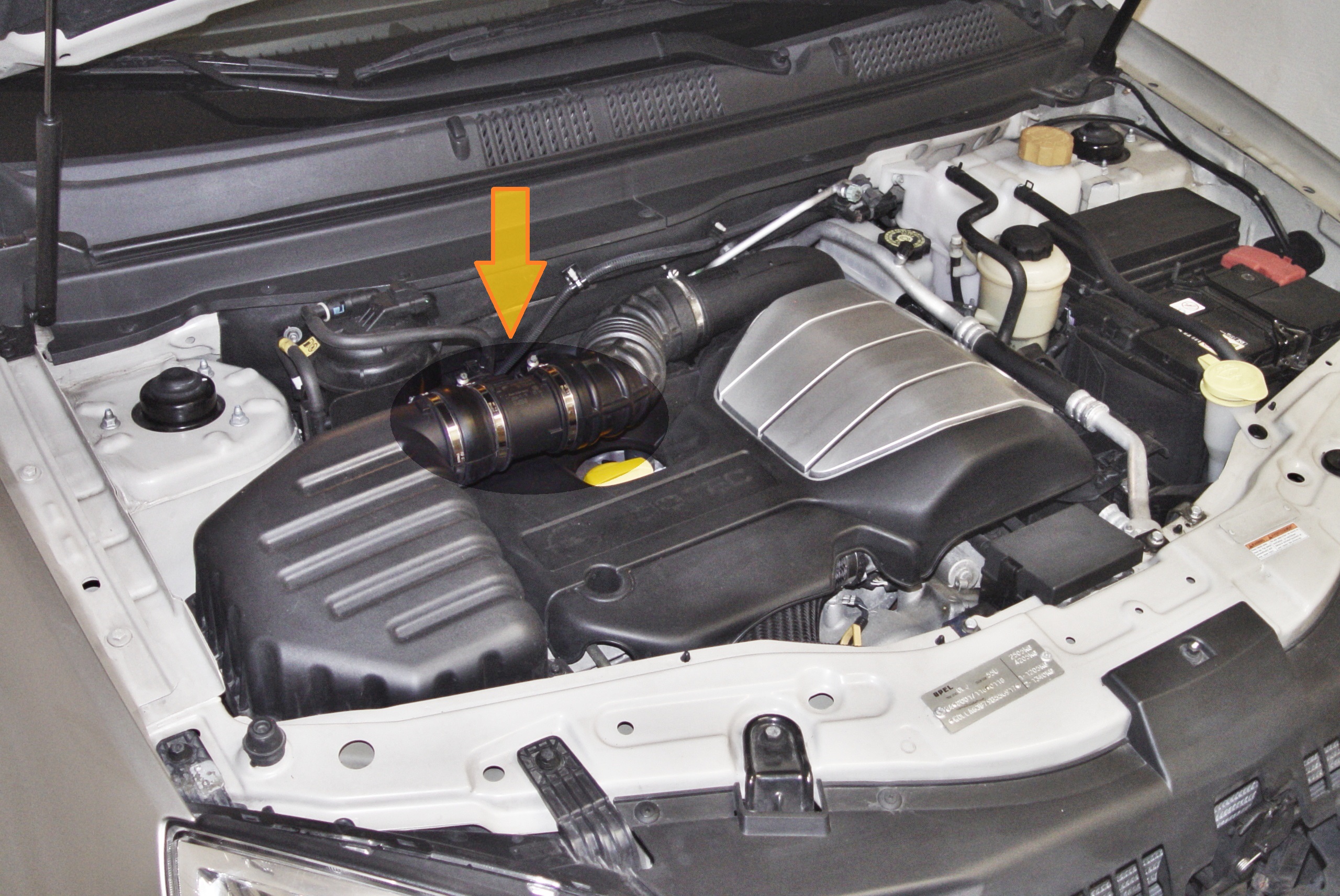
A MAF is often fitted after the air filter and upstream of the engine or turbo inlet, but installations differ. Many use a heated sensing element; airflow affects its heat transfer and the electronics translate this into a signal. Other designs and outputs exist. The ECU may use the measurement for fuelling, load, EGR or other control functions. HELLA's overview describes a hot-film example.
A manifold absolute pressure (MAP) sensor measures pressure at its own location; it is not the same sensor as a MAF. Some vehicles use both, and some calculate airflow without a MAF. Use the correct system diagram.
Practical diagnostic sequence
- Record the complaint. Note when it occurs, engine speed, load, temperature, recent repairs and modifications. Save fault codes and freeze-frame data before clearing them.
- Identify the meter. Check the engine, part number, housing, airflow direction and signal type against the vehicle information. Some meters also include an intake-air-temperature sensor.
- Inspect the air path. With the engine off, check the filter and airbox seating, inlet ducting, breather connections, turbo inlet, charge pipes and clamps. Look for cracks, leaks, restrictions and incorrect assembly. Trace the actual path; not every hose is present on every vehicle.
- Inspect the electrical circuit. Check connector seating, terminals, wiring and supply and ground using the correct diagram. Do not assume pin positions or probe an unidentified circuit.
- Review live data. Record MAF, engine speed and load, temperature, throttle or requested torque, boost/MAP, EGR command and other relevant data during the complaint. Compare with vehicle-specific values and conditions.
- Test the signal. Use the specified meter or oscilloscope procedure for the sensor's analogue, frequency or other output. A changing signal shows response; it does not by itself prove accurate airflow measurement.
- Check for air leaks and restrictions. Use the manufacturer's suitable smoke, pressure or other tests, respecting component limits. A leak or restriction can make a valid sensor reading appear unexpected.
- Confirm the cause. If necessary use an approved comparison or a verified correct sensor and housing. A disconnected sensor may invoke a substitute value, so improved driving alone is not conclusive.
- Repair and retest. Restore all connections, complete any specified adaptation, clear codes when appropriate, then repeat the original test and compare the readings.
Air leaks, restrictions and sensor readings
On a typical upstream MAF arrangement, an intake leak downstream of the meter can admit unmeasured air under vacuum. Under boost, a leak in a pressurised charge path may allow measured air to escape. The effect on fuelling and the signals depends on where the leak is, the operating condition and the ECU strategy; locate and prove the leak rather than diagnosing by a trim or code alone.
A restricted filter, collapsed inlet hose, exhaust restriction, EGR fault or mechanical problem can reduce real airflow. An inaccurate meter can also report too much or too little air. Compare airflow with the manufacturer's expected values at the specified speed, load and temperature, and correlate MAP, boost, EGR and other evidence.
On petrol engines, short- and long-term fuel trims can help identify a mixture correction pattern where supported. They are influenced by many faults and control conditions, so a trim alone cannot condemn the meter. Diesel control strategies differ; do not assume petrol fuel-trim behaviour applies.
Electrical checks and signal types
Some meters provide an analogue voltage; others output a changing frequency or use other signalling. A unit may also output intake-air temperature. Identify each circuit from the wiring and test information. Pico's digital-meter guide notes that airflow and temperature outputs can look similar on a scope but represent different signals.
Check the reference or supply, sensor ground and signal according to the actual design. A shared supply or ground problem can affect several sensors. Compare readings at the sensor and ECU where the procedure calls for it, using suitable probes without damaging terminals. Do not apply battery voltage to an unknown pin.
Fault codes and units
The P0100–P0104 family commonly describes MAF circuit, range/performance, low input, high input and intermittent faults. The exact wording and monitor depend on the vehicle. A low or high electrical input is not automatically proof that actual airflow is low or high.
Scan tools may show air mass in grams per second, kilograms per hour or milligrams per stroke. Grams per second can be converted to kilograms per hour by multiplying by 3.6. A per-stroke value depends on engine speed and the convention used; compare like with like. There is no single idle or full-load MAF value for every engine.
Cleaning, replacement and adaptations
Inspect the filter and the reason for contamination before replacing a meter. Do not touch the sensing element, blow it with compressed air, tap it or use solvents as a general cleaning method. Bosch warns that cleaning or impact can permanently damage some meters; follow the sensor manufacturer's specific instructions.
Use the correct sensor and calibrated housing where specified, with the intended seals, mounting and airflow direction. A physically similar part or mismatched insert can produce a plausible but wrong reading. Reassemble the air path, perform any required adaptation and verify operation. Pico notes that the element and housing form a calibrated unit in the meter it describes; verify the requirements for the actual vehicle.
Related diagnostic guides
- AdBlue and SCR system faults — fluid supply, dosing and SCR efficiency checks.
- NOx sensor faults — NOx measurement, wiring and SCR checks.
- DPF differential pressure sensor faults — pressure hoses, sensor readings and filter restriction.
- Exhaust gas temperature sensor faults — exhaust temperature, wiring and regeneration checks.
- Intake air temperature sensor faults — air temperature, wiring and heat-soak checks.
- Knock sensor faults — knock sensing, wiring and combustion checks.
- Accelerator pedal position sensor faults — pedal input and acceleration response checks.
- Throttle position sensor faults — throttle feedback and response checks.
- Camshaft position sensor faults — starting and crank/cam synchronisation checks.
- Fuel pressure sensor faults — pressure signal and circuit checks.
- Fuel pump faults — supply and rail-pressure diagnosis.
- Injector faults — fuel delivery and cylinder checks.
- DPF faults — soot, pressure sensing and regeneration.
- EGR faults — control and flow diagnosis.
- Turbo diagnostics — includes a worked case where an inaccurate air-mass reading accompanied a boost complaint.
Also see common boost leaks and airflow sensor types.
For manifold pressure, barometric plausibility and boost-sensor checks, see common MAP sensor faults.
Verify the repair
Recheck the air path and electrical connections, clear fault codes when appropriate and repeat the original driving or workshop test. Compare readings under the same conditions and confirm the symptom and relevant codes do not return.