An oxygen sensor, also called a lambda or O₂ sensor, reports information about oxygen in the exhaust. A mixture or sensor fault code does not automatically mean that the sensor is faulty: intake or exhaust leaks, fuelling, ignition, wiring and engine faults can change the reading. Identify the sensor and test the system before replacing it.


Coolant temperature affects warm-up and can influence mixture control. See common coolant temperature sensor faults.
An engine-speed or timing signal fault can accompany a misfire complaint. See common crankshaft position sensor faults.
Symptoms and first checks
| Observation | What to investigate |
|---|---|
| Engine warning light or sensor code | Identify the bank, sensor position, type and exact code; check the circuit, heater, exhaust and mixture. |
| Poor economy, rough running or poor response | Check sensor operation along with intake leaks, fuelling, ignition and engine condition. |
| Lean or rich mixture correction | Review fuel trims, pressure, MAF/MAP plausibility, exhaust leaks and injector operation; a trim is not a sensor test on its own. |
| Sensor slow to become ready | Check the heater circuit, power supply, control and wiring using vehicle-specific data. |
| Catalyst-efficiency code | Check for exhaust leaks, sensor operation and the manufacturer's catalyst test before replacing a sensor or catalyst. |
Bosch's diagnostic guidance lists air or exhaust leaks, fuel pressure and delivery, other sensor inputs and injectors as possible causes behind oxygen-sensor or mixture complaints.
Identify the sensor first
An upstream sensor is generally ahead of the catalyst and may provide mixture feedback. A downstream sensor is generally after the catalyst and can help monitor catalyst performance; exact functions differ. Determine bank and sensor numbering from the manufacturer’s information, especially on multi-bank engines.
A conventional zirconia narrowband sensor changes voltage sharply around stoichiometric mixture. A wideband air–fuel ratio sensor works with a dedicated controller to measure over a broader range. Titania and other designs also exist. Wire count, connector shape or colour alone does not establish the type or pin functions.
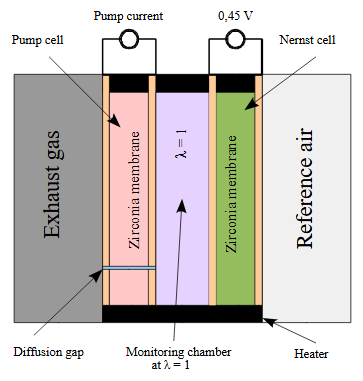

A wideband sensor's raw circuits require the correct controller and test method. Do not interpret its pump-cell or reference circuits using a narrowband switching-voltage rule, apply a supply to unidentified pins or assume all widebands use the same reference arrangement. Pico's Bosch LSU 4.2 explanation is specific to that sensor and controller arrangement.
Practical diagnostic sequence
- Record the complaint. Note cold or hot operation, load, fuel use, misfires, recent exhaust or engine work and modifications. Save fault codes and freeze-frame information before clearing them.
- Identify bank, position and sensor type. Obtain the wiring diagram and the manufacturer's data for the exact vehicle. A pre-catalyst and post-catalyst sensor can behave differently in normal operation.
- Inspect safely. With the exhaust cool, check sensor wiring and connector seating, chafing and heat damage. Inspect the exhaust for leaks, particularly ahead of the affected sensor, and the intake for leaks.
- Check operating conditions. A cold sensor, warm-up strategy, overrun, full-load enrichment or a fault-induced fallback can change closed-loop operation. Confirm readiness and use the specified test conditions.
- Review live data. Where available, log commanded and measured lambda or sensor signals, closed-loop status, fuel trims, engine speed, load and relevant MAF/MAP and fuel-pressure data. Compare like units and banks.
- Check the heater and circuits. Use the correct diagram, equipment and test conditions to check heater supply, control, ground and signal. Resistance tests require the specified isolation and temperature; do not use generic wire colours or universal resistance limits.
- Assess response with an approved test. Follow the manufacturer’s procedure for the sensor type and conditions. If a controlled mixture-change or exhaust-gas test is specified, use appropriate equipment and interpret sensor response and ECU control separately.
- Investigate other causes. Verify intake and exhaust leaks, fuel delivery, injectors, misfires and air-load inputs as indicated. Excess oxygen from a misfire or an upstream exhaust leak can mislead mixture diagnosis.
- Repair and verify. Correct the identified fault and any source of contamination. Complete required adaptations only where specified, then repeat the original test and check fault memory.
Exhaust parts can remain hot long after shutdown. Keep hands, test leads and clothing away from hot and moving components and use suitable exhaust extraction. HELLA's diagnostic guide recommends checking wiring and exhaust leaks before interpreting sensor tests.
Interpreting signals and fuel trims
On a suitable warm, closed-loop petrol system, an upstream zirconia switching sensor typically changes between lean and rich indications as the ECU controls mixture. Its behaviour will change during warm-up, acceleration, overrun or a fault. A downstream sensor is influenced by catalyst operation and should not be expected to mirror the upstream trace continuously.
Fuel trims describe the ECU's corrections under the current control strategy. They help direct further tests, but a high positive or negative trim does not identify one failed component. A leak ahead of the sensor, incorrect fuel pressure, an injector fault, an inaccurate MAF/MAP input or a misfire can alter the feedback. See fuel trims.
A signal that responds to a controlled change shows that the sensor and measurement path respond under that test; it does not prove complete accuracy, heater performance or catalyst health. A scan-tool lambda value may be calculated or substituted in a fault mode. Use the vehicle manufacturer's limits and the correct test for the sensor and position.
Common causes of sensor and circuit faults
- Wiring or connector damage: heat, abrasion, corrosion or poor contact can affect signal or heater circuits.
- Heater fault: an open, short, poor supply or control issue can delay sensor readiness. Test the circuit before replacing the sensor.
- Contamination or thermal damage: oil, coolant, unsuitable additives or sustained incorrect combustion can damage a sensor. The appearance of deposits is a clue, not proof of the source.
- Exhaust leaks: leakage upstream of a sensor can distort its reading; locate and repair the leak.
- Incorrect installation: wrong part, damaged threads, cable contact with the exhaust or contamination of the sensing element can cause further problems.
Sensor-related codes include circuit, heater, slow-response and mixture or catalyst-monitor faults, but exact meaning and bank/sensor identification vary. Use the complete code, manufacturer definition and test plan. Pico's pre-catalyst zirconia guide describes example signal and heater checks and related look-alike faults.
Replacement and verification
Fit the correct sensor for the position and vehicle. Follow the specified removal, thread inspection, tightening and cable-routing instructions; use anti-seize only where and how the manufacturer specifies, and keep contaminants away from the sensing element. Repair the cause of oil, coolant or fuel contamination rather than replacing sensors repeatedly.
After repair, check for exhaust leaks, complete any required adaptations and repeat the original test at the specified operating conditions. Confirm closed-loop status, relevant readings, fault memory and the customer's complaint. A completed catalyst monitor can require the manufacturer's prescribed drive conditions.
Related diagnostic guides
- AdBlue and SCR system faults — fluid supply, dosing and SCR efficiency checks.
- NOx sensor faults — NOx measurement, wiring and SCR checks.
- DPF differential pressure sensor faults — pressure hoses, sensor readings and filter restriction.
- Exhaust gas temperature sensor faults — exhaust temperature, wiring and regeneration checks.
- Intake air temperature sensor faults — air temperature, wiring and heat-soak checks.
- Knock sensor faults — knock sensing, wiring and combustion checks.
- Accelerator pedal position sensor faults — pedal input and acceleration response checks.
- Throttle position sensor faults — throttle feedback and response checks.
- Camshaft position sensor faults — starting and crank/cam synchronisation checks.
- MAP sensor faults and MAF sensor faults — air-load inputs and intake leaks.
- Fuel pressure sensor faults and fuel pump faults — pressure signals and delivery.
- Injector faults — cylinder and fuel-delivery checks.
- DPF faults and EGR faults — aftertreatment and recirculation issues.
- Turbo diagnostics — boost, air-mass and fuelling investigation.
For further detail on the sensors themselves, see lambda sensor operation and wideband oxygen sensor types.