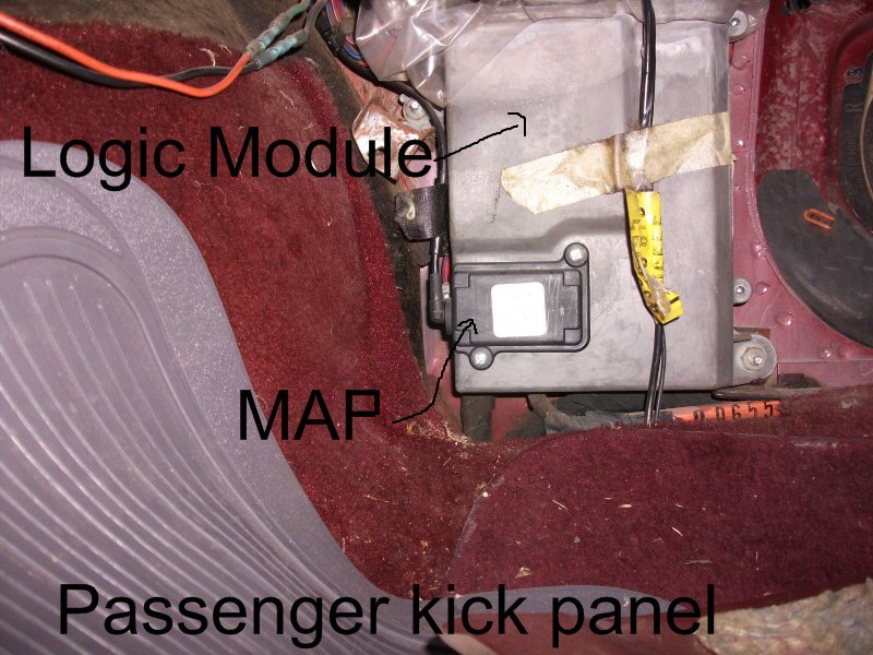
A manifold absolute pressure (MAP) sensor reports pressure at a point in the intake system. A warning light, hesitation or a boost fault can result from the sensor or its circuit, but also from a real air leak, restriction or control problem. Compare the signal with the pressure at the correct location before replacing parts.

MAP and oxygen-sensor signals can both influence mixture control. See common oxygen sensor faults.
Temperature and pressure inputs both inform engine management. See common coolant temperature sensor faults.
Crankshaft signal faults can also cause poor running or starting. See common crankshaft position sensor faults.
Symptoms and starting points
| Observation | Investigate |
|---|---|
| Rough idle, hesitation, misfire or poor starting | Check intake pressure and leaks, sensor signal, wiring, fuelling and mechanical condition. |
| Low power or a boost fault | Compare requested and measured pressure, the sensor circuit, charge-air leaks, turbo control and exhaust restrictions. |
| Sensor signal high, low or intermittent | Check the correct signal, supply, sensor ground, connector and harness before condemning the sensor. |
| Reading plausible electrically but wrong for conditions | Compare against a suitable independent pressure measurement and the vehicle-specific test plan. |
| Temperature fault on a combined sensor | Identify the separate temperature circuit and wiring; the pressure and temperature functions can fail independently. |
These symptoms are not unique to MAP faults. Pico's MAP test includes wiring, blocked sensor ports, air leaks and engine problems among possible causes of unexpected readings.
Where the sensor measures
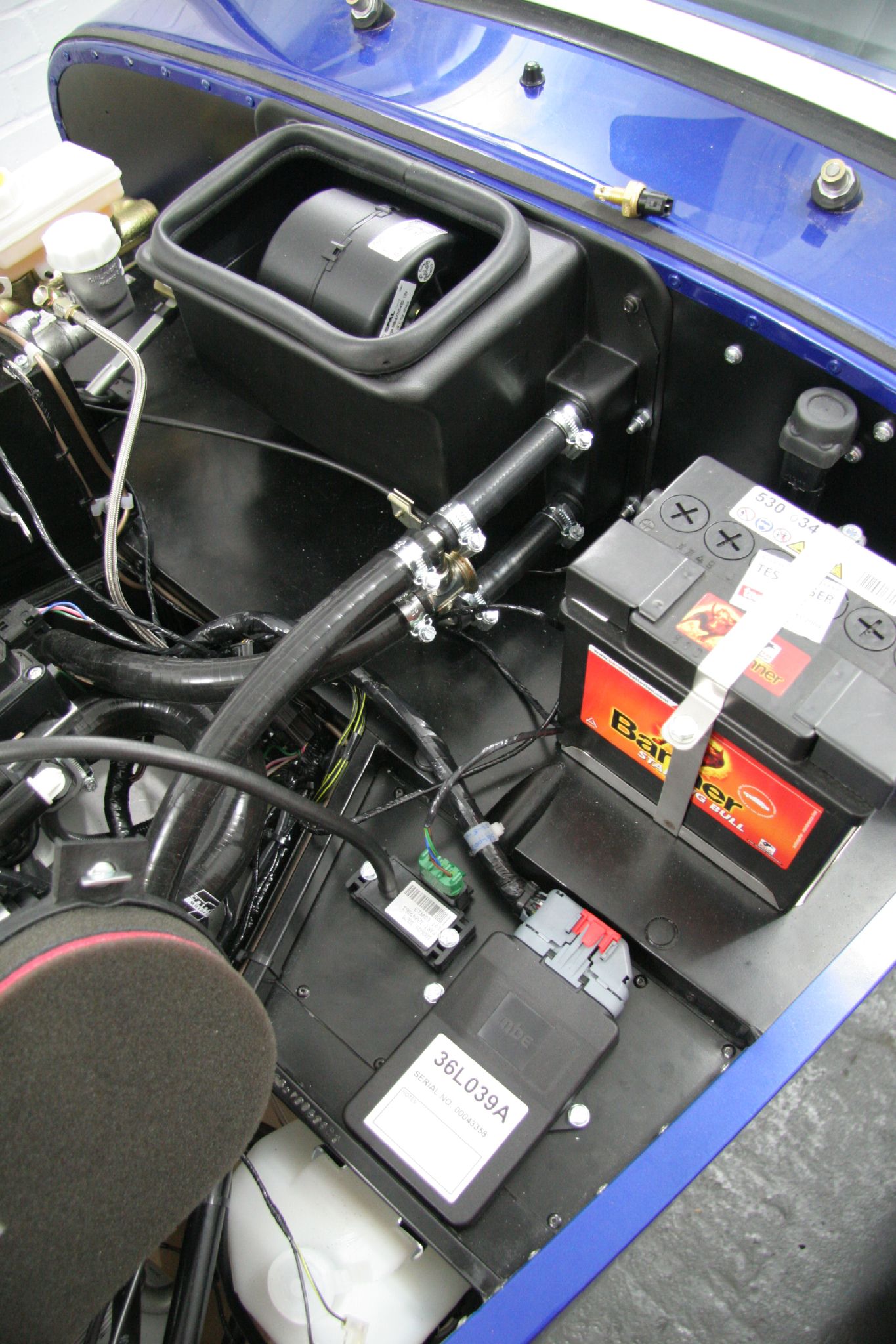

A MAP sensor can be mounted in the manifold or connected by a hose. Some turbocharged vehicles also use pressure sensors elsewhere, such as the intercooler outlet or charge pipe. A combined temperature and pressure sensor is often called a TMAP. The point measured matters: a closed throttle, restriction or pressure drop can make two correctly working sensors read differently. Pico's turbo-diesel example describes several possible TMAP locations.
A MAF sensor measures air mass flow, whereas a MAP sensor measures pressure at its connection. The ECU may use either or both signals for load and fuelling calculations; the presence of a MAF does not make a MAP test redundant.
Absolute pressure and boost
MAP is normally expressed as absolute pressure, referenced to a vacuum. A boost gauge commonly reads pressure relative to the atmosphere. At an illustrative barometric pressure of 100 kPa, a reading of 150 kPa absolute is approximately 50 kPa, or 0.5 bar, gauge boost. Atmospheric pressure changes with weather and altitude; use the actual local value for a precise comparison.
With ignition on and engine stopped, a manifold open to atmosphere should read close to the actual local barometric pressure, subject to the manufacturer's tolerance. A displayed BARO value may be learned, calculated or substituted rather than an independent live measurement; verify its source. A mismatch is a clue to investigate, not proof of which sensor is wrong.
On a throttled petrol engine, manifold absolute pressure normally falls below atmospheric pressure at idle. Diesel and electronically throttled systems can behave differently, and exhaust aftertreatment or EGR operation may alter air-path pressures. Use the correct reference for the operating condition.
Diagnostic sequence
- Record the fault. Note when it occurs, engine speed and load, temperature, modifications and recent work. Save fault codes and freeze-frame data before clearing them.
- Identify the sensor. Confirm which MAP, boost, barometric or combined temperature sensor the fault refers to, its location, output type and wiring diagram.
- Inspect with the engine off. Check connector seating, wiring, damaged seals and, where fitted, a split, blocked or disconnected sensing hose. Follow the manufacturer’s procedure before removing a sensor or disturbing deposits.
- Check key-on plausibility. Compare an atmospheric-exposed sensor's reported absolute pressure with a trustworthy local barometric reference and the specified tolerance.
- Log the fault. Record MAP, barometric pressure where available, requested and actual boost, engine speed, throttle, MAF, temperature and EGR data as relevant. Compare readings at the same operating condition.
- Test the electrical circuit. Identify the correct terminals and use the specified method to check supply, sensor ground and pressure signal. Check related circuits sharing a reference when appropriate; do not short or guess pins.
- Verify pressure independently. If required, compare with a suitable pressure or vacuum transducer connected to the same volume, using the manufacturer’s approved method and correctly rated equipment.
- Follow the evidence. If the sensor reports accurately, investigate real intake leaks, restrictions, turbo control or engine problems. If the electrical circuit or sensor is defective, repair it and verify.
- Retest. Refit with the correct seal, clear faults as appropriate and repeat the original operating test.
Signal, wiring and sensor port
Many MAP sensors have a supply, sensor ground and pressure signal; combined units may also have a temperature circuit. Pinout, voltage range and signal type are vehicle-specific. Some systems use frequency or digital outputs. Use the correct meter or oscilloscope settings, protect connectors and avoid applying a voltage to an unidentified pin.
On a compatible remote-hose sensor, the manufacturer's procedure may permit a regulated hand vacuum or pressure test against a reference gauge. Never exceed the sensor's specified range or assume every sensor tolerates pressure and vacuum in the same way. A blocked port or damaged hose can delay or distort the pressure reaching a sound sensor.
An oscilloscope can reveal dropouts or a slow response, but a changing waveform alone does not prove the pressure calibration is correct. Agreement between scan data and the signal shows how the ECU interprets that signal; an independent reference is needed to check physical pressure when specified. Pico's EGR case study illustrates comparing the MAP signal with a separate pressure transducer.
Common fault codes
P0105–P0109 commonly describe MAP circuit, range/performance, low input, high input and intermittent faults. P0069 can indicate a MAP and barometric-pressure correlation fault. Read the full vehicle-specific definition and conditions. A high or low electrical input does not by itself prove that the physical manifold pressure is high or low.
Common look-alikes
- Air leak or restriction: split hoses, a blocked inlet, intercooler faults or a leaking manifold can change actual pressure. See common boost leaks.
- Turbo or actuator fault: real underboost or overboost can produce an unexpected MAP value. Compare the pressure at the correct location and inspect the control system.
- EGR or engine mechanical fault: these can change the pressure or the ECU's expected airflow without the MAP sensor being defective.
- Shared supply or ground fault: several sensors may report implausible values together; use the vehicle wiring diagram to trace the common circuit.
Cleaning and replacement
Use only the manufacturer's permitted inspection and cleaning methods; do not scrape the sensing element, force debris into the manifold or apply unapproved solvent. Replace damaged seals and use the correct part, pressure range and calibration for the vehicle. A similar-looking sensor may have a different scaling curve. Complete any prescribed learning or adaptation, then check for leaks and repeat the test.
Related diagnostic guides
- AdBlue and SCR system faults — fluid supply, dosing and SCR efficiency checks.
- NOx sensor faults — NOx measurement, wiring and SCR checks.
- DPF differential pressure sensor faults — pressure hoses, sensor readings and filter restriction.
- Exhaust gas temperature sensor faults — exhaust temperature, wiring and regeneration checks.
- Intake air temperature sensor faults — air temperature, wiring and heat-soak checks.
- Knock sensor faults — knock sensing, wiring and combustion checks.
- Accelerator pedal position sensor faults — pedal input and acceleration response checks.
- Throttle position sensor faults — throttle feedback and response checks.
- Camshaft position sensor faults — starting and crank/cam synchronisation checks.
- MAF sensor faults — air-mass signal and intake checks.
- Fuel pressure sensor faults — a separate fuel-system sensor and circuit.
- Fuel pump faults — fuel supply and pressure control.
- Injector faults — cylinder and fuel-delivery checks.
- DPF faults — soot and exhaust differential-pressure checks; this is a different pressure measurement.
- EGR faults — recirculation valve, control and flow.
- Turbo diagnostics — boost measurement and system control.
For pressure-sensor types and calibration, see manifold and boost pressure sensors.