The engine coolant temperature (ECT) sensor helps the engine control unit (ECU) judge warm-up and operating temperature. A bad reading can affect starting, fuelling, idle and other temperature-dependent functions. A low or high temperature reading can also reflect a real cooling-system fault: check the coolant and actual engine temperature as well as the sensor circuit.

Crankshaft signal faults can also cause hard starting or stalling. See common crankshaft position sensor faults.
Symptoms and first checks
| Observation | What to investigate |
|---|---|
| Hard starting, higher idle or poor fuel economy | Compare the ECU's coolant reading with a valid temperature reference; check wiring, sensor, fuel and air systems. |
| Reading stays cold or warm-up is slow | Check actual warm-up, coolant level and thermostat operation as well as sensor plausibility. |
| Reading jumps, stays fixed or is implausible | Inspect sensor connection, wiring, supply and signal; identify whether the scan value is substituted. |
| Overheating warning or coolant loss | Treat as possible real overheating. Check the cooling system and independently assess temperature before blaming a sensor. |
| Fans run unexpectedly or regeneration is inhibited | Check temperature signals and the vehicle's control strategy alongside fan, thermostat and aftertreatment faults. |
These symptoms have multiple causes. HELLA's ECT guidance notes that a failure to reach minimum operating temperature can also be caused by the thermostat.
What the sensor tells the ECU
The ECU uses coolant-temperature information for functions such as warm-up fuelling, idle and, depending on the vehicle, fan or aftertreatment control. Some engines have more than one coolant-temperature sensor, a separate dashboard sender, or separate sensing circuits in one housing. Identify the sensor and data channel before testing.

Many ECT sensors use a negative-temperature-coefficient (NTC) thermistor: its resistance falls as temperature rises. The ECU evaluates the sensor circuit and converts it to a temperature. Some sensors and circuits work differently; use the vehicle’s wiring diagram, signal interpretation and resistance table. Pico's ECT test describes one five-volt-referenced NTC circuit and notes that sensor characteristics are application-specific.
Safety and real overheating
Never remove a radiator or expansion-tank cap while the system is hot or pressurised. Hot coolant and steam can cause severe burns. Let the system cool and follow the manufacturer’s pressure-release procedure before opening it. Keep clear of belts and fans, which can start unexpectedly.
If the vehicle shows an overheat warning, steam or significant coolant loss, stop the engine when safe and follow the handbook. Do not continue running it merely to prove a sensor is wrong. A normal-looking dashboard gauge does not independently prove the engine is cool.
Practical diagnostic sequence
- Record the complaint. Note cold or hot starting, warning lights, fan behaviour, coolant loss, recent work and ambient conditions. Save fault codes and freeze-frame data before clearing them.
- Identify the sensor and channel. Check the engine, wiring diagram and cooling layout. Distinguish the ECU temperature, dashboard indication and any second coolant or radiator sensor.
- Inspect cold. Check coolant level as directed, visible leaks, the connector, pins and wiring. Low coolant or trapped air may affect heat transfer to a sensor as well as engine cooling; investigate the cause.
- Compare after a full cold soak. Before starting, compare ECT with intake-air and ambient readings or a suitable thermometer. They should be broadly plausible for the circumstances, not necessarily identical; sun, engine heat retention and sensor placement matter.
- Observe warm-up. Log ECT over time and compare with an appropriate independent temperature measurement at an accessible point. A fixed, sudden or implausible reading warrants circuit checks; a genuine slow warm-up warrants cooling-system checks.
- Test the circuit. Use the manufacturer’s wiring diagram and test plan to check the reference, sensor ground and signal where applicable. Inspect for intermittent connections without damaging terminals.
- Check the sensor resistance if specified. Isolate the circuit as directed, measure resistance at known sensor temperatures and compare with the exact part's reference table. Never use an ohmmeter on an energised circuit.
- Check the cooling system. If the sensor reading is supported by independent evidence, follow the vehicle-specific checks for thermostat, flow, fan, coolant level and leaks.
- Repair and verify. Fit the correct part and seal if needed, refill and bleed coolant using the specified procedure, then repeat the original starting or warm-up test and check fault memory.
Independent readings need interpretation: an infrared thermometer measures a surface, and emissivity, reflections, sensor position and coolant flow can make it differ from the coolant at the ECT element. Use the manufacturer's chosen comparison point and limits. A scan tool may display a calculated or substitute value when a circuit fails; Pico discusses this limitation.
Reading patterns
| Pattern | What to check next |
|---|---|
| ECT differs greatly from other temperatures after a genuine cold soak | Confirm that the comparison sensors and environment are representative; then check ECT signal and wiring. |
| ECT changes abruptly without a credible physical change | Inspect intermittent wiring, connectors and the signal at the sensor and ECU as specified. |
| ECT agrees with independent measurements but stays low during a suitable warm-up | Investigate thermostat and cooling control using the vehicle procedure. |
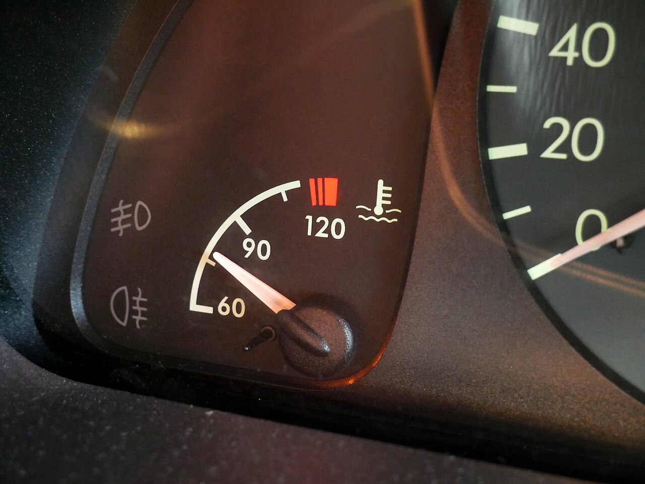
| Gauge and scan tool disagree | Check whether they use separate senders, network data, damping or different locations; neither display alone identifies the failed part. |
| ECT appears fixed at an extreme | Consult the circuit's fault strategy and test for opens, shorts, reference and ground faults. The value may be a substitute. |
Fault codes and related systems
P0115–P0119 commonly describe coolant-temperature circuit, range/performance, low input, high input and intermittent faults. A warm-up or thermostat-related code can have a different cause. Code definitions, thresholds and fallback values vary: use the full manufacturer-specific description and test conditions. A high or low electrical input is not necessarily a high or low actual coolant temperature.
Incorrect temperature information can affect when a petrol engine enters closed-loop control and can influence fuel corrections. On some diesels, a real low operating temperature or implausible signal can prevent or complicate DPF regeneration. These links depend on the engine strategy; an oxygen-sensor or DPF fault is not proof of an ECT fault.
As a scoped example, HELLA describes a Golf V 1.9 TDI BKC where a coolant-temperature fault could accompany poor starting and a misleading boost-related code. Its test values apply to that example, not all sensors.
Replacement and final checks
Use the exact sensor and seal specified for the engine. Similar-looking sensors can have different resistance curves or connector functions. Follow the specified torque and refill and bleed procedure; do not bypass the cooling fan or thermostat. Check for coolant leaks when safe, verify warm-up and fan control under the manufacturer's conditions, and confirm the original symptoms and codes do not return.
For diagnosis of actual overheating or coolant loss, see engine overheating and coolant faults.
Related diagnostic guides
- AdBlue and SCR system faults — fluid supply, dosing and SCR efficiency checks.
- NOx sensor faults — NOx measurement, wiring and SCR checks.
- DPF differential pressure sensor faults — pressure hoses, sensor readings and filter restriction.
- Exhaust gas temperature sensor faults — exhaust temperature, wiring and regeneration checks.
- Intake air temperature sensor faults — air temperature, wiring and heat-soak checks.
- Knock sensor faults — knock sensing, wiring and combustion checks.
- Accelerator pedal position sensor faults — pedal input and acceleration response checks.
- Throttle position sensor faults — throttle feedback and response checks.
- Camshaft position sensor faults — starting and crank/cam synchronisation checks.
- Oxygen sensor faults — mixture feedback and heater circuits.
- MAP sensor faults and MAF sensor faults — air-load inputs and intake checks.
- Fuel pressure sensor faults, fuel pump faults and injector faults — fuel delivery diagnosis.
- DPF faults and EGR faults — aftertreatment and recirculation checks.
- Turbo diagnostics and common boost leaks — air and boost faults.