The diesel particulate filter (DPF) differential pressure sensor helps the engine control unit (ECU) monitor the pressure difference across the filter. The ECU combines this information with other data to assess the exhaust system and manage regeneration. A split or blocked pressure hose, a wiring fault or a faulty sensor can distort the reading; a genuinely restricted or damaged filter can also produce abnormal results. Diagnose the complete measurement system before replacing parts or forcing a regeneration.

Symptoms and first checks
| Observation | What to investigate |
|---|---|
| DPF, engine or glow-plug warning light | Record all codes and freeze-frame data. Identify whether the fault concerns the pressure circuit, filter loading, regeneration or another system. |
| Reduced power or limp mode | Check pressure readings, hoses and sensor circuit, but also investigate genuine restriction, boost, fuel and other engine faults. |
| Frequent, long or unsuccessful regenerations | Review pressure readings, EGT inputs, soot estimates and regeneration conditions. A sensor fault is one possible cause, not the only one. |
| Pressure stays implausibly high with engine stopped | Follow the specified key-on/engine-off zero check. Inspect the sensor, reference, wiring and hose condition; compare against the maker's allowed tolerance. |
| Pressure stays implausibly low or does not respond | Investigate disconnected, split, blocked or crossed hoses, leaks, sensor response and possible filter damage. A low reading does not prove a healthy DPF. |
| Fault after DPF or exhaust work | Check correct sensor, hose routing, taps, fittings and any required adaptation. Follow the vehicle-specific procedure. |
A HELLA Dacia example describes how defective hoses or the sensor can distort the pressure information and reduce performance on the specified vehicles.
What the sensor measures
In a common two-hose design the sensor compares exhaust pressure upstream and downstream of the DPF. The result is a pressure difference, not the same measurement as upstream exhaust back pressure alone. Some vehicles use a different reference arrangement or measure pressure elsewhere. A separate differential pressure sensor may also be used for low-pressure EGR: identify the component and connected points in the relevant wiring and hose diagram. Bosch describes both DPF and EGR applications.
Pressure difference changes with exhaust flow, temperature and the restriction between the measurement points. Soot and ash can increase restriction, but one pressure reading cannot directly tell you an exact soot mass or distinguish soot from ash. A high or low reading must be interpreted at the manufacturer-specified speed, load, temperature and test conditions.
Hoses, pipes and pressure taps
- Split, melted or loose hoses: pressure can leak before it reaches the sensor. Inspect along the entire route and around bends, clips and connections.
- Blocked or restricted taps or hoses: soot, corrosion or water can restrict pressure transmission and produce a slow or misleading response.
- Crossed hoses: reversing upstream and downstream connections can produce an implausible or negative differential reading on systems that report signed values.
- Water or contamination: moisture, oil or deposits can affect the hoses or sensor; inspect as the vehicle procedure directs.
- Electrical faults: damage, corrosion, poor terminal contact, sensor supply, ground or signal faults can make a sound pressure path appear faulty.
Follow the manufacturer's routing, material, length and connection requirements when replacing hoses. Protect the sensor and exhaust components during cleaning; do not blow compressed air through a connected sensor or use an unapproved pressure source. Never assume that visually similar ports can be swapped.
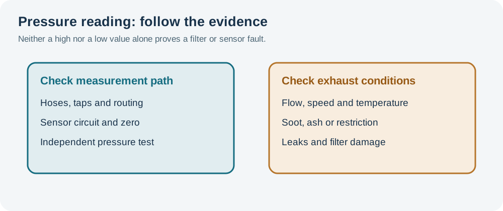
High or low pressure: what could it mean?
| Reading or behaviour | Possible explanations to test |
|---|---|
| High at the specified operating condition | Actual restriction from soot, ash or another obstruction; or a blocked, crossed or leaking measurement path, sensor offset or circuit fault. The effect of a hose fault depends on its location and system design. |
| Low or near zero when a rise is expected | Insufficient flow, leaking or disconnected hose, blocked tap, sensor fault, exhaust leak or a damaged/missing filter are possibilities. Verify the system before drawing a conclusion. |
| Offset with engine stopped | Sensor zero, circuit or ECU value may be incorrect; a small offset may be within specification. Apply only the vehicle's stated test and tolerance. |
| Slow, erratic or fixed response | Check pressure path restrictions, moisture, electrical connections, sensor response and scan-tool update behaviour. |
For an independent measurement use equipment rated for exhaust pressure and temperature, with the correct connections and vehicle procedure. A reading from only the upstream hose is upstream back pressure; it is not automatically the pressure difference across the filter. Pico discusses this distinction. A valid differential comparison requires an appropriate two-point method or the manufacturer's specified equivalent.
Fault codes
P2452 commonly identifies a particulate filter pressure sensor circuit fault, P2453 a range or performance fault, and P2454 a low circuit condition. P2458 and P2459 concern regeneration duration and frequency on some systems. A code may result from wiring, the pressure path, the filter or related conditions. Read the complete manufacturer-specific definition and test plan; an Audi diagnostic reference provides examples for its specified vehicles, not universal thresholds.
Practical diagnostic sequence
- Record the complaint. Save all codes, freeze-frame data, mileage and the conditions in which the fault occurs. Note recent DPF, exhaust, hose or sensor repairs and regeneration history.
- Identify the system. Find the correct DPF pressure sensor, its pressure points, wiring, output type and units. Distinguish it from exhaust back-pressure or EGR differential sensors.
- Inspect safely. Allow the exhaust to cool, secure the vehicle and examine the hoses, pipes, pressure taps, clips, sensor body, connector and wiring. Check routing against the vehicle diagram.
- Check the stopped-engine reading. Use the manufacturer's key-on/engine-off conditions and tolerance for the pressure or sensor-zero check. A specified zeroing procedure may be necessary after certain repairs; do not assume every system permits or requires one.
- Check response and operating conditions. Observe live pressure with the prescribed engine speed and load, along with relevant temperature, airflow and regeneration status. Compare with the exact vehicle limits and test method, not a generic pressure number.
- Test the pressure path. If indicated, inspect the individual hoses and taps for leaks, restrictions, moisture or reversal using approved methods. Isolate the sensor as specified before cleaning a pipe; use the correct hose material and reconnect each port correctly.
- Check the electrical circuit and sensor. Follow the wiring diagram to test the specified reference, ground and signal. Where the manufacturer provides a controlled pressure test, use the correct range and compare the sensor response with a calibrated gauge or transducer. Do not exceed the sensor's rated pressure.
- Verify actual restriction when indicated. Use the approved pressure measurement method and access points, noting whether the instrument measures differential pressure or upstream back pressure. Investigate soot, ash, exhaust leaks, damage and upstream engine faults according to the evidence.
- Repair and verify. Correct the identified fault, perform any prescribed sensor adaptation or reset, and repeat the original conditions. Check codes and regeneration readiness; reset filter replacement or ash data only when the corresponding service has actually been performed and the manufacturer requires it.
Exhaust parts and gases can remain dangerously hot after driving or regeneration. Do not work beneath an inadequately supported vehicle, disconnect hot pressure hoses, or route hot exhaust gases into the workshop. If excessive restriction or overheating is suspected, follow the manufacturer’s safety limits and avoid unnecessary load.
DPF regeneration, soot and ash
A defective pressure sensor or hose can cause the ECU to misjudge conditions for regeneration, but blocked-filter warnings also require checks of the filter and the reason soot accumulated. Temperature sensor faults, engine fuelling, intake or EGR problems and interrupted journeys can be relevant. Regeneration burns soot under suitable conditions; it does not remove accumulated ash. A sensor replacement or adaptation does not clean the filter.


Do not force a regeneration to mask a sensor or hose fault. Follow the vehicle maker's eligibility checks, soot limits, ventilation and fire precautions before any approved service regeneration. See common DPF faults and exhaust gas temperature sensor faults.
Replacement and verification
Use the specified sensor and hoses, connect the pressure ports in their original configuration, and secure the wiring and hoses away from heat and moving parts. Some vehicles require sensor zeroing or adaptation after replacement; use the exact procedure and conditions for that vehicle. Recheck the stopped-engine value and response under the original test conditions, then review codes and aftertreatment status.
Related diagnostic guides
- AdBlue pump faults — reductant supply, pressure and pump checks.
- AdBlue injector and dosing valve faults — dosing, deposits and delivery checks.
- AdBlue and SCR system faults — fluid supply, dosing and SCR efficiency checks.
- NOx sensor faults — NOx measurement, wiring and SCR checks.
- Exhaust gas temperature sensor faults
- Intake air temperature sensor faults
- Knock sensor faults
- Accelerator pedal position sensor faults
- Throttle position sensor faults
- Camshaft position sensor faults
- Crankshaft position sensor faults
- Coolant temperature sensor faults
- Oxygen sensor faults
- MAP sensor faults
- MAF sensor faults
- Fuel pressure sensor faults
- Fuel pump faults
- Injector faults
- DPF faults
- EGR faults
- Turbo diagnostics
- Boost leaks
- Intake air temperature sensors and heat soak