Removed text is struck through; added text is highlighted.
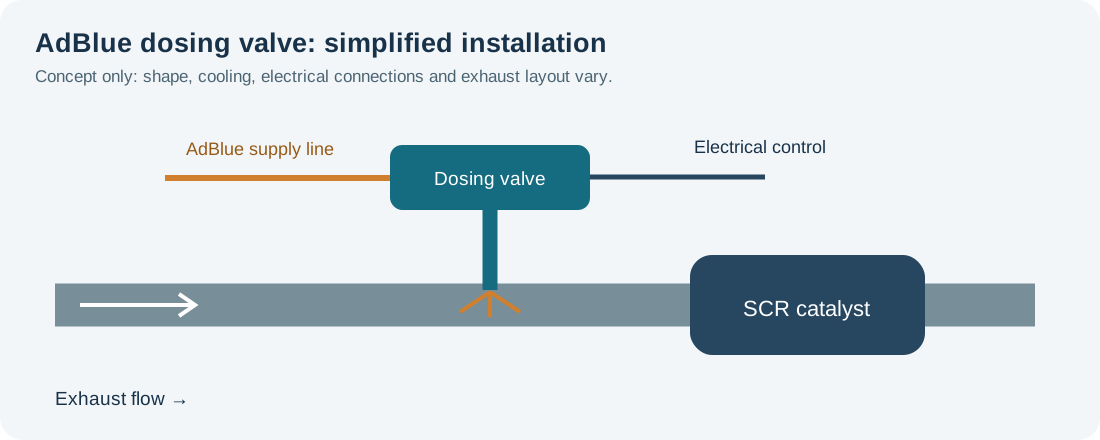
This guide has moved into the combined AdBlue and SCR diagnostic page.Continue to AdBlue injector and dosing valve diagnosis.The AdBlue injector, also called a reductant dosing valve or doser, meters diesel exhaust fluid (DEF) into the exhaust ahead of an SCR catalyst. A dosing fault can be electrical, mechanical or caused by the fluid supply, its lines or the exhaust. Deposits and an SCR warning do not automatically mean the injector has failed: check the complete system and use the vehicle manufacturer's test procedure.Conceptual dosing valve installation. Valve construction, cooling, wiring and exhaust layout vary. Original Tuning Wiki illustration by OpenAI Codex, commissioned for use on Tuning Wiki. Technical basis: Bosch Denoxtronic dosing module.Symptoms and first checksObservationWhat to investigate
SCR, AdBlue or engine warningSave all relevant codes and freeze-frame data. Identify whether the fault concerns the valve circuit, fluid supply, dosing performance, NOx sensors or SCR efficiency.
Restart countdown or reduced performanceFollow the vehicle's displayed instructions and arrange diagnosis promptly. A countdown can have several causes and may need a completed verification after repair.
White deposits around the injector or lineIdentify whether residue is at the tip, a line connection or an exhaust joint. Inspect for leaks and assess deposits using the manufacturer's procedure.
Low or absent dosingCheck fluid quality, supply, pressure, valve command, wiring and the manufacturer-specified dosing test before replacing the valve.
Recurring SCR efficiency faultInvestigate dosing, sensor readiness, exhaust leaks, fluid quality and catalyst conditions. A single NOx or temperature snapshot is not enough to identify the cause.
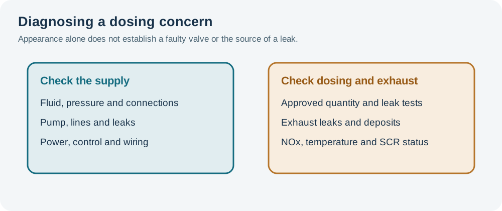
Fault after exhaust or tank workCheck part and installation position, seals, connections, line routing and any required priming or adaptation.How the dosing valve worksThe SCR supply system delivers AdBlue to the dosing module. The controller operates the valve according to the vehicle's exhaust conditions and emissions strategy; the injected fluid forms ammonia that helps the SCR catalyst reduce nitrogen oxides. Dosing conditions, spray pattern and components differ, and some commercial-vehicle valves have cooling arrangements. This is an exhaust aftertreatment injector, not an engine fuel injector. Bosch describes the dosing module and its function.Fluid supply pressure, temperature and dosing command need to be evaluated together. A valve may not be commanded to operate until the relevant conditions are met; a quiet valve at idle or with a cold exhaust is not automatically faulty.Common causes of dosing faultsCheck the supply and electrical control as well as the dosing valve and exhaust. Original Tuning Wiki illustration by OpenAI Codex, commissioned for use on Tuning Wiki.Supply problems: low or contaminated fluid, a pump or pressure fault, blocked line, freezing or a leaking connection can affect delivery.
Electrical faults: damaged wires, loose terminals, corrosion, missing supply or control faults can prevent valve operation.
Valve or nozzle faults: leakage, damage, sticking or deposits may affect a dosing test. Confirm the result under the prescribed test conditions.
Exhaust or installation faults: damaged seals, an exhaust leak, incorrect mounting, wrong part, heat damage or restricted mixing can affect system performance.
Related sensor or catalyst faults: NOx sensors, temperature signals, the SCR catalyst or engine operation may cause an SCR warning even when dosing is correct.White crystals: normal residue or a leak?A small amount of crystallised DEF at a dosing tip can be normal on some systems. A Hino technical tip for specified trucks advises against replacing the injector for tip crystallisation alone. A Volvo truck diagnostic note likewise says minor crystals and a wet valve tip can be normal for the systems it covers. These examples do not establish a universal acceptance limit.Residue at a supply-line connection may instead point to an external leak. A Volkswagen bulletin for affected vehicles identifies a line-connection leak where the prescribed repair concerns the line rather than the injector. Trace the exact source and follow the correct vehicle bulletin; do not diagnose from colour or deposits alone.Fault codes and warningsCodes may identify a reductant injector circuit, dosing performance, reductant pressure, fluid quality or SCR efficiency. P20E8 can indicate reductant pressure too low, while P20EE commonly indicates SCR NOx catalyst efficiency below threshold; neither alone proves an injector fault. See the Volkswagen technical tip and Audi diagnostic reference for examples scoped to their vehicles. Read the complete manufacturer-specific code, suffix, bank and test plan.Practical diagnostic sequenceRecord the complaint. Save all engine and aftertreatment codes, freeze-frame data and warning or countdown information. Note recent refills, exhaust work, sensor replacements and conditions when the fault appears.
Identify the system. Find the correct doser, supply and return arrangement if present, wiring, cooling and vehicle-specific test procedure. Some vehicles have more than one dosing point.
Make the system safe. Let hot exhaust components cool. The fluid system can remain pressurised and may purge after shutdown; wait and depressurise only as directed. Secure the vehicle and follow the prescribed workshop precautions.
Inspect the valve, line and exhaust. Check for damaged connectors, harness chafing, loose fittings, external leaks and deposits. Distinguish residue at the nozzle tip from leakage at a fluid fitting or an exhaust joint.
Check fluid and supply. Confirm the specified fluid and adequate level; if contamination is suspected, use the approved sampling procedure. Review pump operation, line condition and actual versus commanded pressure where supported.
Check electrical control. Use the vehicle wiring diagram and guided fault test for power, ground, control and any relevant communication. Do not apply battery voltage directly to an unidentified valve or probe unspecified pins.
Perform the approved dosing and leak test. Use the manufacturer's diagnostic routine, prescribed pressure, collection equipment and test conditions. Record quantity and response against the exact vehicle limits. Some tests include a purge or bleed phase; interpret leakage only during the phase and conditions defined by that procedure.
Investigate related faults. If supply and dosing pass, assess exhaust leaks, NOx and temperature sensor readiness, engine conditions and SCR efficiency using the specified diagnostic sequence.
Repair and verify. Repair the confirmed leak, circuit, supply or valve fault. Fit specified seals, complete required priming or adaptation, and carry out the prescribed leak check and verification drive or monitor test. Confirm warning and countdown status.Use suitable eye and skin protection and clean, dedicated equipment for DEF. Never disconnect a hot exhaust or pressurised line, spray fluid towards a person, or run an improvised external dosing test. Follow the manufacturer's directions for ventilation, fluid disposal and fire precautions.Dosing quantity, spray and leakageA proper diagnostic test considers supply pressure, valve command, measured fluid quantity and the exact test phase. A result outside the specified quantity can be caused by fluid supply, a restriction, a leak or the valve itself; repeat or isolate tests only as the vehicle procedure instructs. Use the required graduated container and record the result rather than applying a value from another engine.Some procedures also assess leakage or spray characteristics. A wet tip, a small amount released during a bleed or the appearance of a spray are meaningful only in the context of the specific test. The Volvo truck note illustrates why test phase and accurate quantity measurement matter; do not apply its values or criteria to other vehicles.Cleaning, replacement and verificationClean deposits only when the manufacturer approves the method for that component and location. Do not poke the nozzle, use aggressive solvents, scrape sealing surfaces, apply open flame or immerse electronics. If a valve or line must be replaced, use the correct part, new seals where specified and the required fitting torque and routing.After repair, follow the exact priming, leak-check, coding or adaptation instructions. Complete the specified monitor or road test, check SCR data and fault memory, and confirm any restart warning is resolved according to the vehicle procedure. Do not disable emissions controls or clear faults repeatedly in place of a repair.Related diagnostic guidesAdBlue pump faults — reductant supply, pressure and pump checks.AdBlue and SCR system faultsNOx sensor faultsDPF differential pressure sensor faultsExhaust gas temperature sensor faultsIntake air temperature sensor faultsKnock sensor faultsAccelerator pedal position sensor faultsThrottle position sensor faultsCamshaft position sensor faultsCrankshaft position sensor faultsCoolant temperature sensor faultsOxygen sensor faultsMAP sensor faultsMAF sensor faultsFuel pressure sensor faultsFuel pump faultsInjector faultsDPF faultsEGR faultsTurbo diagnosticsBoost leaksIntake air temperature sensors and heat soakCommon diesel engine problems
Page organisation changed
Field
Revision 2
Revision 3
Page type
Technical article
Technical article
Subject
Diagnostics
Reference
Parent
Section level
Section level
Applies to
No ECU-specific applicability
No ECU-specific applicability
Tool groups
None
None
Vehicle makes
None
None
Rendered revisions
Open each version to inspect formatting, tables and photographs.
Revision 2: Common AdBlue injector and dosing valve faults: symptoms, checks and diagnosis
The AdBlue injector, also called a reductant dosing valve or doser, meters diesel exhaust fluid (DEF) into the exhaust ahead of an SCR catalyst. A dosing fault can be electrical, mechanical or caused by the fluid supply, its lines or the exhaust. Deposits and an SCR warning do not automatically mean the injector has failed: check the complete system and use the vehicle manufacturer's test procedure.
Conceptual dosing valve installation. Valve construction, cooling, wiring and exhaust layout vary. Original Tuning Wiki illustration by OpenAI Codex, commissioned for use on Tuning Wiki. Technical basis: Bosch Denoxtronic dosing module.
Symptoms and first checks
Observation
What to investigate
SCR, AdBlue or engine warning
Save all relevant codes and freeze-frame data. Identify whether the fault concerns the valve circuit, fluid supply, dosing performance, NOx sensors or SCR efficiency.
Restart countdown or reduced performance
Follow the vehicle's displayed instructions and arrange diagnosis promptly. A countdown can have several causes and may need a completed verification after repair.
White deposits around the injector or line
Identify whether residue is at the tip, a line connection or an exhaust joint. Inspect for leaks and assess deposits using the manufacturer's procedure.
Low or absent dosing
Check fluid quality, supply, pressure, valve command, wiring and the manufacturer-specified dosing test before replacing the valve.
Recurring SCR efficiency fault
Investigate dosing, sensor readiness, exhaust leaks, fluid quality and catalyst conditions. A single NOx or temperature snapshot is not enough to identify the cause.
Fault after exhaust or tank work
Check part and installation position, seals, connections, line routing and any required priming or adaptation.
How the dosing valve works
The SCR supply system delivers AdBlue to the dosing module. The controller operates the valve according to the vehicle's exhaust conditions and emissions strategy; the injected fluid forms ammonia that helps the SCR catalyst reduce nitrogen oxides. Dosing conditions, spray pattern and components differ, and some commercial-vehicle valves have cooling arrangements. This is an exhaust aftertreatment injector, not an engine fuel injector. Bosch describes the dosing module and its function.
Fluid supply pressure, temperature and dosing command need to be evaluated together. A valve may not be commanded to operate until the relevant conditions are met; a quiet valve at idle or with a cold exhaust is not automatically faulty.
Common causes of dosing faults
Check the supply and electrical control as well as the dosing valve and exhaust. Original Tuning Wiki illustration by OpenAI Codex, commissioned for use on Tuning Wiki.
Supply problems: low or contaminated fluid, a pump or pressure fault, blocked line, freezing or a leaking connection can affect delivery.
Electrical faults: damaged wires, loose terminals, corrosion, missing supply or control faults can prevent valve operation.
Valve or nozzle faults: leakage, damage, sticking or deposits may affect a dosing test. Confirm the result under the prescribed test conditions.
Exhaust or installation faults: damaged seals, an exhaust leak, incorrect mounting, wrong part, heat damage or restricted mixing can affect system performance.
Related sensor or catalyst faults: NOx sensors, temperature signals, the SCR catalyst or engine operation may cause an SCR warning even when dosing is correct.
White crystals: normal residue or a leak?
A small amount of crystallised DEF at a dosing tip can be normal on some systems. A Hino technical tip for specified trucks advises against replacing the injector for tip crystallisation alone. A Volvo truck diagnostic note likewise says minor crystals and a wet valve tip can be normal for the systems it covers. These examples do not establish a universal acceptance limit.
Residue at a supply-line connection may instead point to an external leak. A Volkswagen bulletin for affected vehicles identifies a line-connection leak where the prescribed repair concerns the line rather than the injector. Trace the exact source and follow the correct vehicle bulletin; do not diagnose from colour or deposits alone.
Fault codes and warnings
Codes may identify a reductant injector circuit, dosing performance, reductant pressure, fluid quality or SCR efficiency. P20E8 can indicate reductant pressure too low, while P20EE commonly indicates SCR NOx catalyst efficiency below threshold; neither alone proves an injector fault. See the Volkswagen technical tip and Audi diagnostic reference for examples scoped to their vehicles. Read the complete manufacturer-specific code, suffix, bank and test plan.
Practical diagnostic sequence
Record the complaint. Save all engine and aftertreatment codes, freeze-frame data and warning or countdown information. Note recent refills, exhaust work, sensor replacements and conditions when the fault appears.
Identify the system. Find the correct doser, supply and return arrangement if present, wiring, cooling and vehicle-specific test procedure. Some vehicles have more than one dosing point.
Make the system safe. Let hot exhaust components cool. The fluid system can remain pressurised and may purge after shutdown; wait and depressurise only as directed. Secure the vehicle and follow the prescribed workshop precautions.
Inspect the valve, line and exhaust. Check for damaged connectors, harness chafing, loose fittings, external leaks and deposits. Distinguish residue at the nozzle tip from leakage at a fluid fitting or an exhaust joint.
Check fluid and supply. Confirm the specified fluid and adequate level; if contamination is suspected, use the approved sampling procedure. Review pump operation, line condition and actual versus commanded pressure where supported.
Check electrical control. Use the vehicle wiring diagram and guided fault test for power, ground, control and any relevant communication. Do not apply battery voltage directly to an unidentified valve or probe unspecified pins.
Perform the approved dosing and leak test. Use the manufacturer's diagnostic routine, prescribed pressure, collection equipment and test conditions. Record quantity and response against the exact vehicle limits. Some tests include a purge or bleed phase; interpret leakage only during the phase and conditions defined by that procedure.
Investigate related faults. If supply and dosing pass, assess exhaust leaks, NOx and temperature sensor readiness, engine conditions and SCR efficiency using the specified diagnostic sequence.
Repair and verify. Repair the confirmed leak, circuit, supply or valve fault. Fit specified seals, complete required priming or adaptation, and carry out the prescribed leak check and verification drive or monitor test. Confirm warning and countdown status.
Use suitable eye and skin protection and clean, dedicated equipment for DEF. Never disconnect a hot exhaust or pressurised line, spray fluid towards a person, or run an improvised external dosing test. Follow the manufacturer's directions for ventilation, fluid disposal and fire precautions.
Dosing quantity, spray and leakage
A proper diagnostic test considers supply pressure, valve command, measured fluid quantity and the exact test phase. A result outside the specified quantity can be caused by fluid supply, a restriction, a leak or the valve itself; repeat or isolate tests only as the vehicle procedure instructs. Use the required graduated container and record the result rather than applying a value from another engine.
Some procedures also assess leakage or spray characteristics. A wet tip, a small amount released during a bleed or the appearance of a spray are meaningful only in the context of the specific test. The Volvo truck note illustrates why test phase and accurate quantity measurement matter; do not apply its values or criteria to other vehicles.
Cleaning, replacement and verification
Clean deposits only when the manufacturer approves the method for that component and location. Do not poke the nozzle, use aggressive solvents, scrape sealing surfaces, apply open flame or immerse electronics. If a valve or line must be replaced, use the correct part, new seals where specified and the required fitting torque and routing.
After repair, follow the exact priming, leak-check, coding or adaptation instructions. Complete the specified monitor or road test, check SCR data and fault memory, and confirm any restart warning is resolved according to the vehicle procedure. Do not disable emissions controls or clear faults repeatedly in place of a repair.