AdBlue, also called diesel exhaust fluid (DEF), is used by selective catalytic reduction (SCR) systems to reduce nitrogen oxide emissions. A warning can result from low or contaminated fluid, a supply or dosing fault, a sensor or wiring problem, an exhaust leak, or catalyst performance. Read the fault information and test the system before replacing the tank, pump or NOx sensors.
Symptoms and first checks
| Observation | What to investigate |
|---|---|
| Low AdBlue warning | Check the vehicle's required fluid, minimum refill quantity and recognition procedure. A low-level warning may differ from an SCR malfunction warning. |
| SCR, emissions or engine warning | Record all engine and aftertreatment codes and freeze-frame data. Check fluid supply, sensor and dosing faults and relevant service information. |
| Restart countdown or restricted operation | Follow the vehicle's displayed instructions and arrange diagnosis promptly. The countdown may remain until the underlying fault is repaired and the specified verification completes. |
| Warning remains after topping up | Confirm the correct fluid, required refill quantity and recognition conditions. A level sensor, fluid-quality, wiring or unrelated SCR fault can also be present. |
| White deposits around a line or injector | Inspect for leaks, damaged seals, deposits and incorrect dosing using the manufacturer’s procedure. Residue alone does not prove an injector or catalyst is faulty. |
| Repeated fault after parts replacement | Recheck wiring, fluid condition, exhaust leaks, correct part numbers, dosing operation and any required coding or adaptation. |
Warnings and restart strategies depend on the vehicle and fault. A HELLA Audi A5 example describes fluid level, leaks and a possible software issue for specific vehicles. A countdown is not proof that the tank assembly has failed.
How the SCR system works
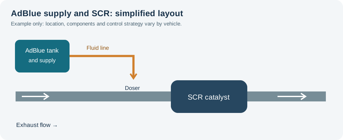
The system stores a high-purity urea-water solution in a separate tank. A supply system delivers it to a dosing valve, which introduces controlled amounts into the exhaust. The resulting ammonia helps the SCR catalyst convert nitrogen oxides into nitrogen and water. Sensors and control modules monitor system conditions and performance. Designs differ: tank, pump, heater, filter, sensors and electronics may be separate or integrated.
Many vehicles have NOx sensors and exhaust temperature sensors at different points. The ECU uses their information together with other operating data; sensor warm-up and exhaust temperature affect when certain checks can run. Some systems use multiple SCR catalysts or dosing points. See Bosch NOx sensor information and the NOx sensor diagnostic guide.
Common causes of faults
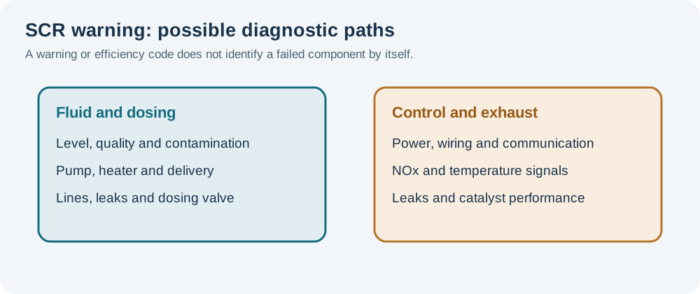
- Fluid level or quality: insufficient fluid, incorrect or contaminated fluid, or a level/quality sensor fault can cause warnings.
- Tank and supply: a pump, pressure sensor, filter, heater, frozen line or electrical fault can prevent the commanded delivery. Component layouts and serviceable parts vary.
- Lines and dosing valve: leaks, blocked lines, damaged connections, deposits or a faulty dosing valve can affect delivery.
- Wiring and communications: corrosion, water ingress, damaged harnesses, blown fuses, power or ground faults and network problems can affect any SCR module.
- Sensor and exhaust faults: NOx or temperature sensor problems, exhaust leaks, incorrect engine-out emissions or catalyst deterioration can produce a performance warning.
- Software or configuration: an applicable manufacturer bulletin, control-unit update, adaptation or correct part identification may be relevant after the other causes have been checked.
Fault codes: use the complete description
P20EE is commonly associated with SCR NOx catalyst efficiency below the expected threshold; P204F can refer to reductant system performance, and P20E8 to reductant pressure too low. Manufacturer definitions, suffixes, bank identification and diagnostic conditions vary. These codes describe a detected condition, not a guaranteed failed component. A Volkswagen technical tip lists P20EE and P204F for its specified vehicles. HELLA's Peugeot Boxer bulletin gives a model-specific P20EE example and calls for system checks before considering its listed software remedy.
Practical diagnostic sequence
- Record the complaint. Save the complete codes, freeze-frame data and warning or countdown from engine and aftertreatment controllers. Record recent refills, repairs and relevant vehicle conditions before clearing codes.
- Identify the system and check service information. Obtain the exact layout, fault-code procedure, tank and dosing arrangement, repair bulletins and relevant software requirements for the vehicle.
- Check the fluid. Confirm the level and refill procedure. If quality or contamination is suspected, use the manufacturer-approved sampling and test method. A concentration reading alone may not identify every contaminant.
- Inspect the installation. With the exhaust cooled and the system in the specified safe state, check the tank, lines, connectors, wiring and exhaust for leaks, damage, deposits and insecure mounting. Do not disturb a pressurised line.
- Check power and data. Test fuses, supply, grounds and communication at the relevant modules according to the wiring diagram and fault tree. A missing message can have a network or supply cause.
- Review live data. Check level, fluid temperature or quality, commanded dosing, supply pressure, sensor readiness, NOx readings and exhaust temperatures as supported. Account for warm-up and enabling conditions; do not compare a single reading with a generic threshold.
- Test delivery and dosing. Use the manufacturer’s guided pressure, leak, quantity or actuator test with the specified equipment, containers and precautions. Separate a pump or supply fault from a dosing valve, wiring or line fault before replacing components.
- Assess conversion performance. If dosing is correct but an efficiency fault remains, follow the prescribed checks for exhaust leaks, NOx sensor plausibility, temperature, engine operation and the SCR catalyst. An instantaneous upstream/downstream comparison alone does not prove catalyst failure.
- Repair and verify. Correct the identified cause, carry out any required priming, adaptation, coding or reset, and complete the manufacturer’s verification procedure or drive cycle. Confirm fault memory and warning status, including any countdown.
AdBlue lines may remain pressurised and some systems purge fluid after the ignition is switched off. Wait and depressurise only as the manufacturer directs before disconnecting anything. Exhaust parts can remain very hot after operation or regeneration. Use suitable eye and skin protection, ventilation and spill-cleaning procedures.
Fluid, filling and contamination
Use fresh, vehicle-approved AdBlue/DEF meeting the specification in the owner’s manual, from a clean, sealed or suitable dedicated dispenser. Do not dilute it, add additives or transfer it using containers previously used for fuel, oil or other chemicals. Follow the vehicle's instructions for filler location and refill quantity.
If AdBlue is put into the diesel fuel tank, or diesel is put into the AdBlue tank, do not switch on the ignition or start the engine. Arrange recovery or specialist help and follow the manufacturer’s contamination procedure; operating pumps can spread contamination. Do not assume a simple top-up or dilution is an adequate repair.
AdBlue can freeze in cold conditions. Freezing alone does not prove the tank or pump has failed: systems may have heaters and specific cold-weather operating strategies. If a warning persists after the prescribed conditions are met, test the heater, temperature sensor, supply and control circuit. Bosch describes a heated supply module as one example; arrangements differ by vehicle. Bosch supply module information.
Deposits, dosing and catalyst efficiency
White residue can indicate crystallised fluid from a leak or deposits near the dosing point, but visual appearance alone cannot identify the cause. Check fluid lines and fittings, dosing quantity and spray characteristics, exhaust temperature and any relevant service bulletin using approved methods. Do not scrape, soak or heat a dosing valve unless the manufacturer permits it.
An SCR efficiency fault can arise from sensor errors, exhaust leaks, incorrect fluid delivery, engine-out emissions or catalyst deterioration. Compare upstream and downstream NOx data only when the relevant sensors are ready and the vehicle-specific monitor conditions are satisfied. Use the manufacturer’s guided assessment rather than replacing a catalyst based on one scan-tool snapshot.
After repair
Use the correct components and seals, route lines and wiring as specified, and perform any manufacturer-required priming, leak check, software configuration or adaptation. Clear faults at the appropriate step and complete the required verification drive or stationary test with the prescribed safety measures. Confirm that the warning and countdown have cleared according to the vehicle procedure; do not bypass or disable emissions controls.
Related diagnostic guides
- AdBlue injector and dosing valve faults — dosing, deposits and delivery checks.
- NOx sensor faults
- DPF differential pressure sensor faults
- Exhaust gas temperature sensor faults
- Intake air temperature sensor faults
- Knock sensor faults
- Accelerator pedal position sensor faults
- Throttle position sensor faults
- Camshaft position sensor faults
- Crankshaft position sensor faults
- Coolant temperature sensor faults
- Oxygen sensor faults
- MAP sensor faults
- MAF sensor faults
- Fuel pressure sensor faults
- Fuel pump faults
- Injector faults
- DPF faults
- EGR faults
- Turbo diagnostics
- Boost leaks
- Intake air temperature sensors and heat soak
- Common diesel engine problems