Race Technology supplies vehicle data-acquisition, display and analysis equipment for motorsport and testing. The DL1 CLUB is a standalone logger, while DASH displays provide a separate way to see selected data in the car. Hardware options and enabled functions vary by model and unit.
DL1 CLUB / DL1 MK3
The manufacturer's DL1 CLUB introduction identifies DL1 CLUB and DL1 MK3 as the same product. Its GPS and accelerometers can record vehicle motion; other data such as engine speed, wheel speeds, temperatures and pressures requires the appropriate sensors, interfaces and configuration. It has no integrated in-car display. A compatible Race Technology dash can be added.
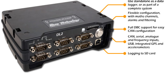
Other models
Race Technology's hardware documentation also lists DL1 SPORT, DL1 PRO, DL1 WP and DL2. The cases, connectors and features differ; consult the exact model documentation, including options, rather than assuming they are interchangeable. The manufacturer describes the DL2 as a logger with GPS/GLONASS, accelerometers, sensor inputs, CAN/serial ports and SD storage, with enhancement options.
Displays, ECU data and analysis
The DASH2 displays data from a compatible logger. The manufacturer explains that DASH2 PRO lap timing requires a DL1/DL2 or its GPS and data-logging option. Check whether a particular display has independent logging enabled.
For ECU channels, Race Technology documents direct ECU interfaces and an OBD-II adapter route; support, available channels and rates depend on the ECU, interface and configuration. Analysis software can compare sessions and plot channels; some advanced features require unit-linked licences.
Live reporting
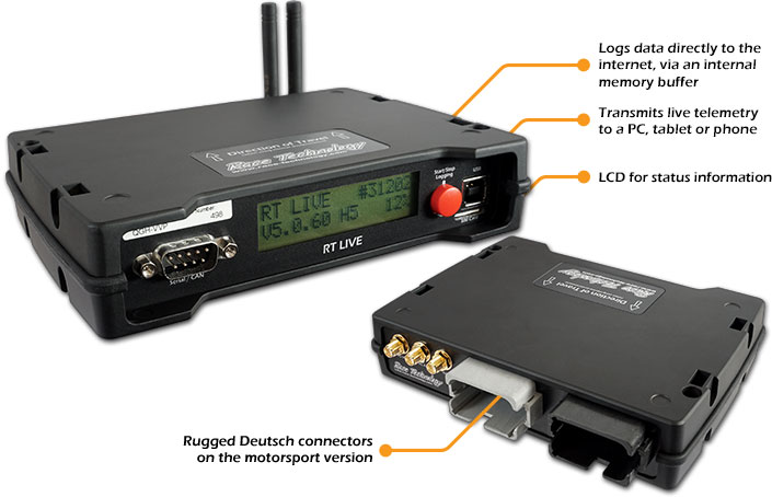
RT LIVE Industrial is described by its manufacturer as an online logger using 4G LTE, with browser and PC access to recorded data; connected CAN data requires a CAN licence. Mobile coverage, service arrangements and configuration should be checked for the intended deployment. It is a different product from an ordinary DL1 installation.
Model and capability reference
Race Technology's range includes older units as well as more recent models. These descriptions identify documented variants; check current supply, hardware revision and individual unit options rather than assuming each model is still sold.
| Model | What it does | Connections and qualifications |
|---|---|---|
| DL1 FD | Standalone logger with GPS, sensor inputs and removable SD storage. The listed GPS output is 5 Hz; 20 Hz raw data is stored for post-processing. | Manufacturer lists 12 analogue inputs and four frequency inputs. Its CAN port receives CAN 2.0B and CAN FD. Analogue sampling is listed as 100 Hz standard and 1 kHz optional; check licences and the channel source. |
| DL1 SPORT | Compact standalone GPS and accelerometer logger without an integrated screen; records to CompactFlash. | Manufacturer documents eight analogue inputs, an RPM input and serial output to a compatible display. Sensors and configuration determine available channels. |
| DL1 CLUB / MK3 | Standalone GPS and inertial logger; CLUB and MK3 identify the same model in the manufacturer's documentation. | Can send data to a compatible dash and log connected engine and chassis signals. Confirm installed options, interfaces and memory-card requirements for the unit. |
| DL1 PRO, DL1 WP and DL2 | The manufacturer describes the PRO and WP as CLUB-feature loggers in different enclosures. The PRO uses an aluminium case and water-resistant connectors; the WP uses a waterproof enclosure and downloads via USB. DL2 has a larger enclosure for accessible connections. | Check the specific unit's options and environmental rating. The manufacturer describes DL2 GPS/GLONASS, accelerometers, CAN/serial ports, sensor inputs and SD logging on its industrial range page. |
DASH display models
- DASH2: displays data from compatible Race Technology loggers and gives driver warnings and lap information when connected to suitable sources. It should not be assumed to record internally. DASH2 introduction.
- DASH2 PRO: display with stand-alone inputs and optional internal GPS/data-logging provision. The manufacturer's documentation specifies 8 GB when its logging option is enabled, with USB download; it may also work with an external logger. Check the installed option and antenna rather than assuming every DASH2 PRO logs. DASH2 PRO introduction; logging instructions.
- DASH5 PRO: configurable display with multiple screens and alarms. Its documentation describes controls for an external logger and an internal-memory logging option when enabled. Verify options on the individual display. DASH5 PRO operation; logging controls.
RT LIVE product variants
RT LIVE Motorsport is an online logger and telemetry device for racing. Its manufacturer describes a 4G LTE connection, live browser or PC viewing of lap and vehicle data, and buffering when the mobile connection is lost. It needs the correct power, antennas, SIM/service and configuration; ECU or sensor channels and available licences depend on the installation. Live telemetry guide.
RT LIVE Industrial is marketed for remote monitoring and field testing, with 4G LTE online logging, browser or PC access and optional connected sensors; its listed CAN data function requires a CAN licence. The products and service arrangements must be checked for the region and intended application. A local serial connection to a dash is not itself remote telemetry.
Analysis workflow
Step-by-step: download and analyse a recorded run
This example uses a DL1 FD and Race Technology Analysis for Windows. Other loggers use different storage or transfer methods; use the individual model page and manual for the correct route. A DASH without the relevant logging option needs a separate logger.
- Install the software. Download and install the Race Technology software package on a supported Windows PC; open Analysis and choose the default layout if prompted.
- Retrieve the run. Stop logging first. On a DL1 FD, remove its SD card and insert it into the computer's card reader. Its files are
.RUNrecordings in date-named folders. For a DL1 WP, use Device Explorer over its USB lead; for RT LIVE V2, use the configured cloud account. Other models may use CompactFlash or another method. DL1 FD guide; DL1 WP transfer; RT LIVE V2. - Load the data. In Analysis choose File → Load Logged Data, select the local card, PC, connected device or cloud source as applicable, choose the run and open it. Follow the prompt to process data if shown. Loading data.

Race Technology Analysis: choose File → Load Logged Data. The interface may vary by version. Image: Race Technology, reproduced with permission; source and guide. 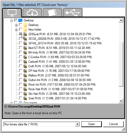
Race Technology Analysis: select the .RUN recording and choose Open; tabs offer different data sources. Image: Race Technology, reproduced with permission; source and guide. - Inspect the run. Open the track map and a graph. Select GPS speed as a first channel, then add throttle, RPM or brake pressure only if those channels were actually recorded. Confirm the units and signal quality before interpreting them.
- Set laps if necessary. If the session has no correct lap marker, add a start/finish marker across the track on the map, with the arrow pointing in the direction of travel. Add sectors as needed and open the lap and sector times table. Getting started.
- Compare laps. Select two laps in the lap and sector table, use the graph command and choose speed versus distance. Look at the same corner or braking zone in each trace, then check other recorded channels and the track map for context. DL1 FD comparison walkthrough.

Race Technology Analysis: selected channels and overlaid acceleration and speed traces. Example recorded channels may differ. Image: Race Technology, reproduced with permission; source and guide. - Keep or share the analysis. Save the analysis or export the relevant data using the available File options. Video and advanced GPS processing may require a licence for the recording device; confirm options for the unit. Licence information.

Race Technology Data Analysis is the Windows application for examining recorded runs from compatible Race Technology equipment. The manufacturer lists channel graphs, track maps, lap and sector analysis, comparisons, calculated variables and filtering, plus DBC-based CAN variable handling where applicable. Video and data can be analysed together when supported and enabled. Manufacturer analysis software guide.
Getting started: download the Race Technology software package, transfer the recording using the logger's documented SD or USB method, then load the run in Analysis and compare laps, traces and track position. The manufacturer lists Windows systems in its system requirements. The software package is free to download; the manufacturer says some advanced video and GPS processing features require a licence tied to the logger. Confirm current licence terms and compatibility with the particular logger. Analysis licence information.
Live versus recorded: RT LIVE and compatible series systems can also provide browser-based live data and downloads, subject to access and service arrangements. Race Technology's team-access guide describes Live Monitor for live data and Analysis for full recorded-data review on a Windows PC.
Configure the inputs and recording rates, confirm GPS lock and check that sensor units and scaling are plausible. Download a short test before relying on a full session. Race Technology Analysis can overlay sessions and create graphs and track maps; some advanced analysis features require a licence tied to the logging unit. Video synchronisation and expansion functions depend on the product and relevant licence.
Product photographs and references
Race Technology's product page shows manufacturer photographs of DL2 and RT LIVE. Credit: Race Technology. Images remain with their owner; the linked page is not a grant of a reuse licence.
See also In-car datalogging and telematics for system selection and interpreting recordings.
Pinouts and cabling
Use the exact model and hardware version: Race Technology has used different connectors across DL1 generations and RT LIVE variants. Pin numbers below are taken from the device connector drawings in the cited manufacturer documents. Match the moulded cavity numbers and the indicated view to the actual connector. Verify the required options, the ECU protocol and all electrical limits before powering a connection.
DL1 CLUB / DL1 MK3 — rear nine-way D-sub
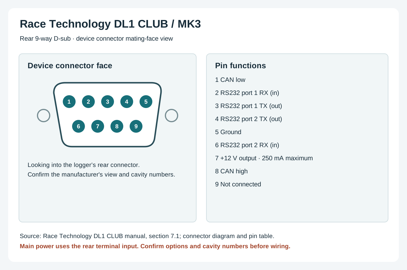
The manufacturer identifies DL1 CLUB and MK3 as the same device. Its rear-panel connector carries CAN, serial communication and a limited auxiliary supply; it is not a generic RS232 PC pinout. See the DL1 CLUB connection diagram and manual, section 7.1; use the numbered diagram on the rear view.
| Pin | Function |
|---|---|
| 1 | CAN low |
| 2 | RS232 port 1 RX (data in) |
| 3 | RS232 port 1 TX (data out) |
| 4 | RS232 port 2 TX (data out) |
| 5 | Ground |
| 6 | RS232 port 2 RX (data in) |
| 7 | +12 V output (250 mA limit) |
| 8 | CAN high |
| 9 | Not connected |
The DL1 CLUB rear screw-terminal markings include A1–A8 analogue inputs, A9–A12 configurable inputs/low-side outputs, rL and rH/rG RPM connections, F1–F4 frequency inputs, two +5 V references, ground and a 9–24 V power input. See the manufacturer's label table for ratings and the particular output option. The 9-way pin 7 is an auxiliary output; do not treat it as the main supply input. The CAN or second-serial option may require the supplied breakout cable.
RT LIVE v2 Motorsport and Industrial — front nine-way D-sub
For RT LIVE v2, Race Technology lists the following on the front-panel 9-way connector. Although much looks similar to DL1 CLUB, pin 7 is specified as “power output” in the v2 guide; do not assume the DL1 CLUB current limit or the older RT LIVE wiring applies. Refer to the manufacturer's v2 connection diagrams for connector view, power ratings and the specific harness.
| Pin | Function |
|---|---|
| 1 | CAN low |
| 2 | RS232 1 RX |
| 3 | RS232 1 TX |
| 4 | RS232 2 TX |
| 5 | Ground |
| 6 | RS232 2 RX |
| 7 | Power output |
| 8 | CAN high |
| 9 | Not connected |
RT LIVE v2 Motorsport — rear connectors A and B

The manufacturer's v2 Motorsport rear-panel drawing gives the following 12-way assignments. A denotes analogue inputs and O denotes low-side driver outputs; entries marked with both depend on configuration. These assignments are not the RT LIVE v2 Industrial 25-way connector or the earlier RT LIVE. See the v2 Motorsport connections and verify the exact cable, supply and limits.
| Pin | Connector A | Connector B |
|---|---|---|
| 1 | A1 | A5 / O1 |
| 2 | A3 | A7 / O3 |
| 3 | RS232 RX | Status |
| 4 | RPM high level | CAN high |
| 5 | 12 V power in | 12 V power in |
| 6 | 5 V sensor supply | Trigger |
| 7 | Lap trigger | iButton |
| 8 | Ground | Ground |
| 9 | RPM high-level ground | CAN low |
| 10 | RS232 TX | RPM low level |
| 11 | A4 | A8 / O4 |
| 12 | A2 | A6 / O2 |
On v2 Industrial the manufacturer separately lists a two-pin LEMO power connector: pin 1 positive, pin 2 ground. Its 25-way connector is model-specific; use the cited drawing rather than the Motorsport A/B table.
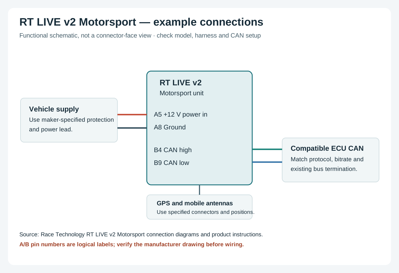
Practical cable selection
- Choose an ECU-specific CAN, serial or OBD interface and its required licence; a physical connector alone does not guarantee protocol or channel support. Race Technology ECU connection guidance.
- Use the correct sensor type and supply, calibrate channels in the configuration software and check grounds and continuity with power disconnected. For RPM, follow the manufacturer's high- and low-level input guidance for the specific ignition system.
- Use the specified GPS and mobile antennas for the model, and secure looms away from heat and moving components. Consult the particular product's wiring and power documentation rather than assuming all RT LIVE versions share a loom.
Individual model pages
Model-specific specifications, connector references and wiring guidance: