A wideband sensor measures both sides of lambda 1
A wideband oxygen sensor, also called a broadband or air-fuel-ratio sensor, measures exhaust oxygen from rich mixtures through to free air. Bosch’s LSU technical information describes it as a planar zirconia dual-cell limiting-current sensor with a heater. A control unit holds the sensing cell at its setpoint by driving a pump current. That current is the measurement. On the LSU 4.2 characteristic it is about zero near lambda 1, negative when the mixture is rich and positive when the mixture is lean, and it keeps moving out to free air.
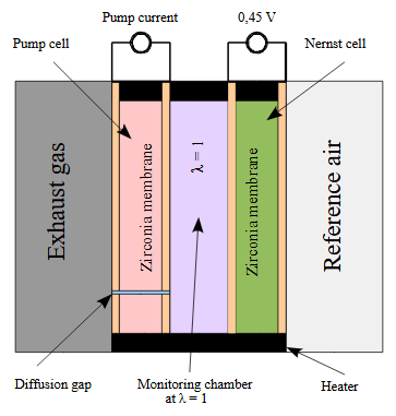

A narrowband switching sensor does not do this. Its voltage steps at lambda 1 and stays on one side or the other, so closed loop can only hold the mixture on that step. The mixture page explains that limit, and how a gas analyser calculates lambda from the exhaust gases instead: Mixture tuning: AFR and lambda.


The sensor does not produce a lambda number on its own. The LSU 4.2 and LSU 4.9 technical informations say the sensor operates only with a matching control unit, and they name the AWS box, the LA4 and the CJ125 integrated circuit as examples. Those units do not turn the same pump current into the same output voltage. The LSU 4.2 sheet prints both conversions. With pump current Ip in milliamps, the AWS voltage is 2.5 + 1.648 × Ip. The CJ125 voltage is 1.5 + (61.9 / 1000 × v) × Ip, and v is switched between 17 and 8. At zero pump current the AWS output sits at 2.5 V and the CJ125 output sits at 1.5 V. Read the lambda the controller publishes. A raw voltage borrowed from a different controller is a different scale.
Bosch LSU 4.2
The LSU 4.2 technical information, Y 258 E00 019e of 20 February 2006, gives a monotonic range of lambda 0.7 to free air, for gasoline and diesel exhaust. The nominal heater voltage is 9 V. The approximate 10 W figure in that sheet is the heater power at 7.5 V, at thermal equilibrium in air, not the power at the 9 V nominal voltage. Cold heater resistance for a new sensor, including the cable and connector, is 3.2 Ω at room temperature, and at least 1.8 Ω at −40 °C. A workshop check in the same sheet, grey wire to white wire, sensor unplugged, is 2.5 Ω up to but not including 5 Ω at room temperature. The guide value for light-off after the heater is switched on is 20 seconds or less.
The connector module contains a trimming resistor. The circuit drawing labels it 30 Ω to 300 Ω. It defines the sensor’s characteristic and is required for it to function. The same document forbids a direct 24 V supply unless a voltage converter is used. Maximum system supply is 16.5 V. Effective heater voltage is held to 3 V while condensation is possible, then to 12 V continuous, with 13 V allowed for 30 seconds at a time and 200 hours accumulated. The minimum heater-control frequency in this sheet is 2 Hz. The heater is ramped by the control unit. It is not tied across the battery.
Temperature is held by measuring the Nernst-cell resistance Ri with a small AC signal of 1 kHz to 4 kHz. For a new LSU 4.2 at the operating point that resistance is 80 Ω. The AC current used for the measurement is limited to 250 µA. Pump current into the cell is limited to no more negative than −9 mA on a rich signal at lambda 0.7 or above, and no more than 6 mA in air. The sheet also warns that the characteristic moves when the test gas changes, especially the hydrogen fraction, and that the effect is stronger on the rich side than on the lean side.
The nominal line in that sheet is for named synthetic gases: a rich mixture of 9% CO, 7% H2 and 7% CO2 in nitrogen, and lean mixtures of oxygen in nitrogen. Zero pump current is printed at lambda 1.009. The same line gives −1.85 mA at lambda 0.70, −1.08 mA at lambda 0.80, −0.47 mA at lambda 0.90, 0.95 mA at lambda 1.70, 1.40 mA at lambda 2.42 and 2.55 mA in air.
The connector carries six functions. The wire colours follow the functions. On the RB150 and RB130 connectors the pin numbers run in opposite order.
| Function | Colour | RB150 pin | RB130 pin |
|---|---|---|---|
| Pump current, APE / IP | Red | 1 | 6 |
| Virtual ground, IPN / VM | Yellow | 2 | 5 |
| Heater minus, H− | White | 3 | 4 |
| Heater positive, H+ | Grey | 4 | 3 |
| Trim current, RT | Green | 5 | 2 |
| Nernst voltage, RE | Black | 6 | 1 |
Operating exhaust temperature is 930 °C or below. Above that the heater is switched off and the reading is of limited accuracy. A short allowance reaches 1,030 °C, for at most 250 hours accumulated. Hexagon temperature is 570 °C in operation and 650 °C on that same short allowance. The connector is held to 120 °C, and the cable and protective sleeve to 250 °C. Fuel is specified as commercially available unleaded fuel to DIN EN 228. Exhaust pressure changes the signal. The technical information plots that shift against absolute pressure.
Bosch LSU 4.9
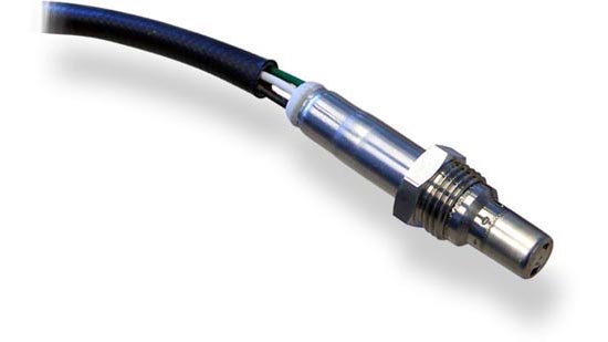
The LSU 4.9 technical information, Y 258 E00 015e of 14 June 2005, is the same kind of sensor with a wider rich limit: lambda 0.65 to free air, again for gasoline and diesel. The nominal heater voltage is 7.5 V, and the heater power at that voltage is about 7.5 W at equilibrium in air. Cold resistance is the same 3.2 Ω nominal, and 1.8 Ω minimum at −40 °C, as the 4.2 sheet. The guide value for light-off is 10 seconds or less. The Nernst-cell resistance at the operating point is 300 Ω for a new sensor, measured the same way, against 80 Ω on the LSU 4.2. A controller that regulates temperature to the wrong resistance heats the wrong sensor to the wrong temperature.
The circuit drawing again labels the trim resistor as 30 Ω to 300 Ω, the Nernst reference as 450 mV, and a continuous reference pump current of 20 µA. Pump-current limits match the form of the 4.2 sheet: no more negative than −9 mA on a rich signal at lambda 0.65 or above, and no more than 6 mA in air. It is not a plug swap for an LSU 4.2. The heater rating, the rich-end range, the Nernst resistance and the connector differ, and the trim resistor belongs to that individual sensor.
The 2005 sheet lists one six-pin order. Red, yellow, white, grey, green and black are pump current, virtual ground, heater minus, heater positive, trim current and Nernst voltage, on pins 1 to 6 in that order. That is the RB150 order from the 4.2 sheet. The 4.9 document does not mention an RB130 reversal, and the Motorsport data sheet repeats pins 1 to 6 with the same functions. Use the connector the controller was built for.
The 2005 nominal line, on the same style of synthetic gas as the 4.2 sheet, puts zero pump current at lambda 1.016, −2.22 mA at lambda 0.65, −1.11 mA at lambda 0.80 and 2.54 mA in air. The later Bosch Motorsport LSU 4.9 data sheet prints a different series and adds the CJ125 output voltage. In that sheet, zero pump current falls at lambda 1.003 and both CJ125 gains read 1.500 V there. The sheet says v = 17 is the gain typically used for lean mixtures and v = 8 the gain typically used for rich mixtures. UA is the evaluation-circuit voltage. Only the pump current belongs to the sensor. Selected rows from that sheet:
| Pump current Ip | Lambda | CJ125 UA, v = 17 | CJ125 UA, v = 8 |
|---|---|---|---|
| −2.000 mA | 0.650 | not printed | 0.510 V |
| −1.602 mA | 0.700 | not printed | 0.707 V |
| −1.243 mA | 0.750 | 0.192 V | 0.884 V |
| −0.927 mA | 0.800 | 0.525 V | 1.041 V |
| −0.405 mA | 0.900 | 1.074 V | 1.299 V |
| 0 mA | 1.003 | 1.500 V | 1.500 V |
| 0.329 mA | 1.179 | 1.846 V | 1.663 V |
| 0.938 mA | 1.701 | 2.487 V | 1.964 V |
| 2.150 mA | 7.506 | 3.762 V | 2.565 V |
| 2.250 mA | 10.119 | 3.868 V | 2.614 V |
The same Motorsport sheet states accuracy of 0.80 ± 0.01 at lambda 0.8, 1.016 ± 0.007 at lambda 1, and 1.70 ± 0.05 at lambda 1.7. Applying the LSU 4.2 sheet’s AWS formula to the −0.927 mA row gives about 0.97 V, against 0.525 V or 1.041 V on the two CJ125 gains. Same sensor current, three voltages.
Absolute exhaust pressure in the 2005 sheet is 2.5 bar continuous. A short-time allowance reaches 4 bar, for at most 250 hours accumulated over the sensor’s life. Beyond the stated pressure the accuracy can be limited. Continuous exhaust temperature is 930 °C or below, with 1,030 °C for at most 250 hours accumulated. Hexagon temperature is 600 °C in that sheet. The connector limit is 120 °C in the 2005 technical information and 140 °C in the Motorsport data sheet. The Bosch Motorsport data sheet repeats the 0.65-to-air range, allows gasoline, diesel and E85, and names the LT4 as an example of the control unit. That LT4 is the LSU control unit in the Motorsport range. The LT4 ADV further down this page is the unit for the LSU ADV sensor.
During the condensation phase the 4.9 sheet limits effective heater voltage to 2 V. Water hitting the hot ceramic cracks it. Continuous heater voltage is then held to 12 V, with 13 V for 30 seconds and 200 hours accumulated. The minimum heater-control frequency is 20 Hz in the 2005 technical information and 100 Hz in the Motorsport data sheet. Those are different Bosch documents. A controller follows the limit it was designed to.
Bosch Motorsport sells the LSU 4.9 with two connectors. Order 0258.017.025 has the automotive connector 1928.404.687, mating part D261.205.356-01, and a 95 cm cable. The Motorsport connector version, order B261.209.358-03, uses AS607-35PN, mating part AS007-35SN, with cable lengths from 20 cm to 90 cm. The automotive connector is a series part and is not sold separately by Bosch Motorsport. Thread is M18 × 1.5, wrench size 22 mm, tightening torque 40 Nm to 60 Nm, and weight without the wire is 75 g. System supply on that sheet is 10.8 V to 16.5 V. The heater supply remains the 7.5 V nominal, not the system voltage.
The reference air on an LSU 4.9 is the volume inside the PTFE formed hose. The 2005 sheet says that hose is kept sealed and undamaged. Minimum bend radius is 20 mm on the long hose and 12 mm on the short hose, and the first cable fixing sits 200 mm to 400 mm after the hose. Wax, tar and spray oil are kept off the sensor and the connector.
Bosch LSU ADV
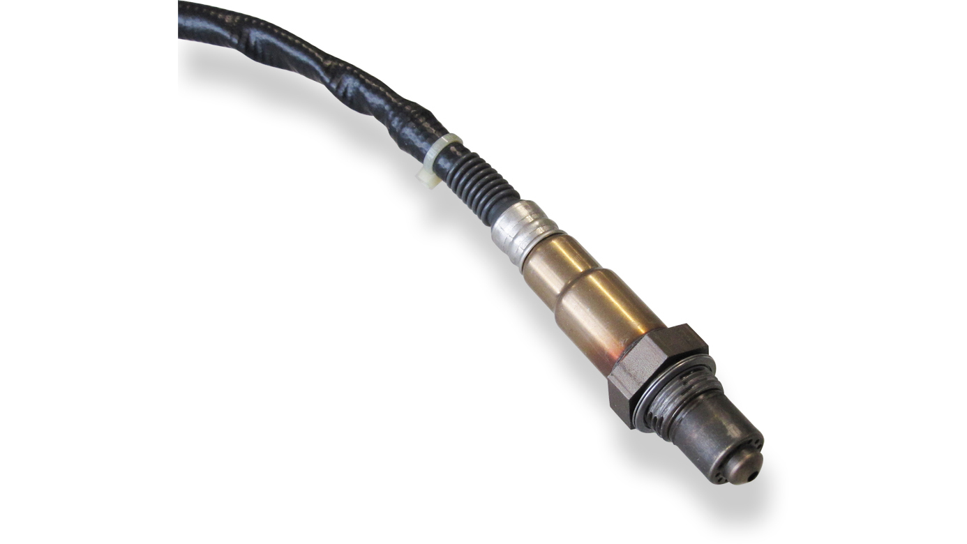
The Bosch Motorsport LSU ADV data sheet describes the same dual-cell limiting-current principle, with a monotonic range of lambda 0.65 to free air, for gasoline, diesel and E85. Exhaust pressure is 2.5 bar or below for stated accuracy, operating exhaust temperature 930 °C or below, and a short peak of 1,030 °C. The hexagon of the sensor may run up to 650 °C in operation and 700 °C for a short time. Thread is M18 × 1.5 and weight without the wire is 75 g. Bosch describes the working temperature range as wider than the LSU 4.9.
The difference that matters in the wiring is the connector. LSU ADV has no trimming resistor, and only five pins are connected. The sensor sheet says it operates only with the evaluation unit used in the LT4 ADV lambda control unit. The LT4 ADV page describes the sensing arrangement as a Nernst cell and a pump cell, with the gas between the Nernst cell and an internal oxygen reference chamber held at lambda 1.013. That page also credits the sensor with a shorter heating time and less influence from ambient pressure than earlier LSU sensors. An LSU 4.9 channel, including one built around the CJ125 gain table above, is a different evaluation unit. A five-pin ADV sensor in a six-pin 4.9 harness does not become a 4.9 sensor.
Bosch Motorsport also lists an LSU ADV pre-turbo variant on the same lambda-sensor overview: lambda 0.65 to free air, M18 × 1.5, hexagon 650 °C, and a higher operating exhaust temperature of 980 °C, with the same 1,030 °C short peak. This page does not have a separate pressure rating for that variant.
Other Bosch planar sensors
The Motorsport overview lists a Mini-LSU 4.9 with the same lambda 0.65 to free air and the same 930 °C operating exhaust temperature, on an M16 × 1.5 thread. Weight without the wire is 34 g, and the hexagon rating on that listing is 700 °C. It does not fit an M18 bung.
ETAS’s ES63x modules, described with the controllers below, also name Bosch LSU 4.7 and Bosch LSU 5.1. ETAS calls the LSU 5.1 a lambda lean sensor and says it needs adjustable limits on the Nernst and pump voltages. This page has no Bosch characteristic curve for the LSU 4.7 or the LSU 5.1. A lean sensor is the wrong part when the mixture is rich of lambda 1.
The current Bosch CJ125 and CJ135 product pages name an LSU 5.2 among the sensors those integrated circuits can be configured for. This page has no Bosch sensor data sheet for the LSU 5.2, so it does not state a range, a heater power or a connector for it. A controller menu that adds “LSU 5.2” is a setting for that part. It is not a new name for an LSU 4.9.
NTK and NGK wideband sensors
NGK and NTK are not two competing sensor principles on this page. NGK Spark Plugs (UK) Ltd’s 2022 lambda catalogue is the NTK range, and the wideband section is written as the NTK ZFAS-U type. Niterra’s wide-range oxygen sensor page describes the same ZFAS-U family and the interface chip that goes with it. A box sold as NGK, with an NTK part number, is this family. It is not a Bosch LSU with a different label.
ZFAS-U and ZFAS-U2
The catalogue identifies the ZFAS-U type as a UEGO, wideband or linear sensor. Apart from the part number, the practical identification is the lead count: usually at least five wires, and always heated. The element is two ceramic substrates, a zirconia detection element and an alumina heater. The detection cavity sees the exhaust through a gas diffusion layer. The sensor pumps oxygen in or out of that cavity to hold a stoichiometric mixture there, and the pump current is the measure of the exhaust. The catalogue points to lean-burn engines and to diesel engines, which run with excess air, as uses of that wider window, and also to tighter control around stoichiometric.
The construction difference from the LSU 4.2 and LSU 4.9 is the reference. The NGK catalogue says no external reference air is required, because the sensor generates its own. Niterra’s description of the ZFAS-U says the same thing and adds that the design is fully sealed and waterproof. The LSU 4.9 PTFE hose is a reference-air volume and is kept intact for that reason. Sealing an NTK connector the way one would try to waterproof an LSU reference path is a different mechanical problem. Sharing an M18 thread with an LSU does not make the pump current, the heater or the connector compatible.
Niterra’s product text for the ZFAS-U2, also carried on NGK Spark Plug’s distributor listing, describes it as the later wide-range sensor: accurate across its measurement range, sealed, and active in about 5 seconds because the heater and the element are one ceramic structure. It still requires the special interface. ETAS names the ZFAS-U2 as a broadband sensor supported by the ES63x modules, alongside the Bosch types. This page still does not quote a manufacturer lambda span for the ZFAS-U2 itself. The ETAS module span of lambda 0.6 to 16 is the module’s range, and ETAS says the actual values depend on the individual sensor curve.
The catalogue’s heater check for heated sensors, those with three or more wires, is a resistance measurement after the heater pair has been identified. Above 30 Ω the heater is failed. An open circuit, infinite resistance, is a broken heater or a broken wire. That 30 Ω figure is the catalogue’s failure threshold. It is not a nominal resistance, and it is not the Bosch cold-heater figure of about 3.2 Ω. The Bosch check and the NTK check are for different sensors.
| Function in the NGK catalogue | Typical 5-wire colours, type A | Typical 5-wire colours, type B |
|---|---|---|
| Heater, Vh− | Yellow | White |
| Heater, Vh+ | Blue | Grey |
| Sense, Vs+ | Grey | Black |
| Pump, Ip+ | White | Red |
| Sense and pump common, Vs/Ip− | Black | Yellow |
The catalogue calls these typical colours. A vehicle-specific sensor still has to be identified by its part number and connector. The catalogue’s case for the vehicle-specific part is the connector, the insertion depth and the protection tube, and it says every NTK type in that range was certified by TÜV against the original-equipment part. Its fitting notes also say the anti-seize already on the thread is the compound to use, because another paste can poison the element. Torque in that catalogue is 35 Nm to 45 Nm for an M18 × 1.5 thread and 18 Nm to 23 Nm for M12 × 1.25. That M18 figure is the NTK catalogue’s, not the 40 Nm to 60 Nm on the Bosch Motorsport LSU 4.9 sheet.
Part numbers in the NGK catalogue
The 2022 catalogue’s part-number key reads an example such as OZA446-E30 as an oxygen sensor, then a zirconia element (Z; T would be titania), then the thread or the wideband generation. A is an 18 mm thread and D is 12 mm. L is linear wideband, generation I. UA is linear wideband, generation II. The new-part list in that edition contains both OZA numbers and a long run of UAA and UAR numbers. The UA prefix is the catalogue’s mark for the second-generation linear sensor. Matching a UAA or UAR number to a vehicle still means the connector, the wire count and the catalogue row, not the prefix alone. This page does not treat every UAA number as a ZFAS-U2.
NTK’s own interface chip, and a sensor with the controller in the plug
Niterra lists the XCU-UA as the single-chip interface between a ZFAS-U and the vehicle processor. It contains the ZFAS-U control circuitry and the element-temperature control, it speaks SPI, and it has basic on-board diagnostics for open and shorted terminals. That is the NTK chipset a control-unit designer buys, in the same role as the Bosch CJ125 and CJ135 below.
The same page describes the ZFAS-U2-SM. The control module is built into the connector, the compensation for that sensor is already stored there, and the signals leave on CAN. Niterra says this removes the need to develop a separate interface and that the module uses the ZFAS-U element. A CAN wideband of this type is a different part from a five-wire ZFAS-U2 that expects an external controller.
Controllers
The number on a gauge is the controller’s scale, after it has closed the pump loop and read the current. The LSU 4.9 table above is one scale, the CJ125 UA voltage. Innovate and AEM publish gasoline air-fuel-ratio voltages that are not that UA voltage. ETAS publishes a configurable 0 V to 10 V output. A 2.5 V signal means a different mixture on each of them.
Innovate LC-2 and MTX-L
Innovate’s LC-2 manual 11-0137C and MTX-L manual 11-0129B describe controllers for the Bosch LSU 4.2 and the Bosch LSU 4.9. From firmware that exposes the sensor menu, LM Programmer selects the sensor type, and a free-air calibration is then required with the sensor out of the exhaust. Innovate’s sensor part in those manuals is 3737 for the LSU 4.2 and 3888 for the LSU 4.9. The cables differ. LSU 4.9 cables are marked “4.9” on the connector. The manuals say a spliced cable, or the wrong sensor type for the sensor fitted, can permanently damage the sensor and can damage the controller.
The LC-2’s default analogue outputs, from that manual, are a wide channel and a narrow one. The yellow wire is 0 V at 7.35 AFR and 5 V at 22.39 AFR. The brown wire is 1.1 V at 14 AFR and 0.1 V at 15 AFR. Those are gasoline AFR numbers in the manual. LM Programmer can change the fuel type. They are not the CJ125 voltages in the LSU 4.9 table, and they are not lambda. The LC-2 needs a switched 12 V supply that can provide 3 A, fused at 5 A, and a ground shared with anything reading the analogue voltage. Innovate’s placement notes in the same manual put the bung at least 24 inches after the exhaust port or the turbo, between the 9 o’clock and 3 o’clock positions, and hold the bung temperature to 500 °C. An unpowered sensor left in a running exhaust is damaged. The MTX-L manual uses the same sensor selection. Innovate’s multi-sensor guide 11-0144 extends that LSU 4.2 and LSU 4.9 choice to the LM-2 and the SCG-1 as well.
AEM X-Series
AEM’s 30-0300 X-Series UEGO manual for the Bosch sensor is written around the LSU 4.9. The kit list includes sensor 35-2004, described as a Bosch LSU 4.9, and a sensor cable marked for that sensor. The gauge window in the manual is 8.0:1 to 20.0:1 AFR, which the manual also writes as lambda 0.55 to 2.00. That window is the display. It is smaller than the LSU 4.9’s published range out to free air. A reading of four dashes is the manual’s indication of a mixture leaner than 20:1, including free air and fuel cut.
The 0 V to 5 V output is differential. AEM prints AFR = (2.3750 × volts) + 7.3125 and lambda = (0.1621 × volts) + 0.4990, with the output considered valid from 0.50 V. At 0.50 V the manual’s table reads lambda 0.58 and 8.50 AFR. Above 4.50 V is a sensor error. The gasoline AFR display uses a stoichiometric ratio of 14.65. The manual tells the user to switch the display to lambda for E85, methanol, ethanol or CNG, because AFR on that face is lambda multiplied by 14.65. AEMnet is CAN at 500 kbit/s, 29-bit identifiers 0x00000180 through 0x0000018F, 100 Hz, with lambda packed as 0.0001 lambda per bit. The gauge has no CAN termination of its own. A separate RS-232 stream at 9,600 baud repeats the number on the display, and the manual says that stream matches the earlier 30-4100 and 30-4110 gauges. Each sensor needs its own controller. The manual names the AEM 30-2340 as the four-channel alternative.
A later 30-0300 manual for the AEM/FAE sensor adds automatic detection. The gauge shows FAE or LS4.9 according to which sensor is plugged in. This page has no element specification for the FAE sensor beyond that manual. The Bosch LSU 4.9 remains the sensor the earlier 30-0300 manual is written for. AEM prefers the trim resistor’s laboratory calibration and treats free-air calibration as the alternative when a sensor is suspected of contamination. The manual’s damage list matches the Bosch limits on several points: leaded fuel, silicone, oil, coolant, a rich mixture that soots the element, shock, and exhaust above 930 °C. Supply is held to 16 V.
Bosch Motorsport LT4 and LT4 ADV
The LSU 4.9 Motorsport sheet names the LT4 as a suitable controller. The LT4 product specification now provides a direct reference: up to four LSU 4.2, LSU 4.9 or Mini-LSU 4.9 channels, with CAN and configurable analogue outputs. The function-sheet and logging details below distinguish the controller configuration from the raw sensor characteristic.
The Lambdatronic LT4 ADV is documented on its own. It supplies up to four LSU ADV sensors and no other type. Its stated application range is lambda 0.75 to 5. The LSU ADV sensor sheet still runs from lambda 0.65 to free air, so the control unit’s published window is the narrower of the two. Outputs are CAN, at 500 kbaud or 1 Mbaud, and four 0 V to 5 V analogue channels. Resolution is 2.5 × 10⁻⁴ lambda, and the sample rate and the CAN refresh are 100 Hz. Supply is 10 V to 14 V, with operation from 6.5 V, a short maximum of 26 V, 5 A in service and 26 A while the four heaters are coming up. Bosch recommends no more than 1.5 m of cable from sensor to unit. The reference ground has to land on the measuring device or on system ground, and the offset between power ground and reference ground is held to 2 V. Order number on that sheet is F02U.V01.111-04. Configuration is RaceCon.
ETAS ES63x, and the earlier LA4
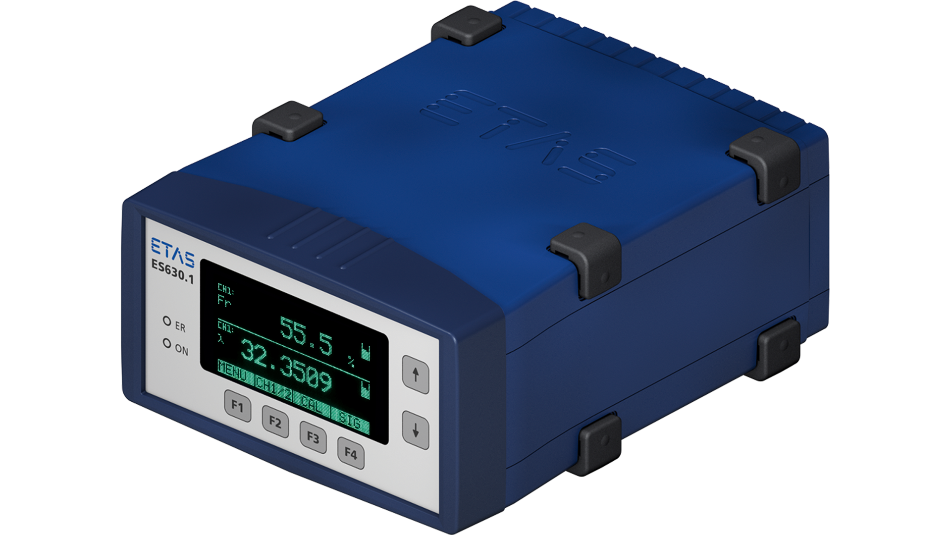
The ES630 and ES635 are single-channel. The ES631 and ES636 are two-channel. ETAS lists Bosch LSU 4.2, LSU 4.7, LSU 4.9, LSU 5.1, LSU ADV-G and NTK ZFAS-U2. The sensor type is coded in the adapter cable, or in the LSU ADV and LSU 5.1 sensors ETAS supplies, and the module reads that code so the wrong sensor is not driven as another type. The LSU 5.1 is identified there as a lean sensor. The LSU ADV and the LSU 5.1 need adjustable limits on the Nernst and pump voltages.
The modules’ own measuring span is lambda 0.6 to 16, reciprocal lambda 1.67 to 0.0625, air-fuel ratio 8.5 to 200, and oxygen 0% to 25%. Pump current is recorded from −10 mA to 10 mA at up to 2 kHz. ETAS notes that these minimum values depend on the characteristic of the individual sensor. The LSU technical informations limit pump current to about −9 mA and +6 mA, so the module span is not a claim that every connected sensor measures 0.6 to 16. An analogue output, one channel or two, is an isolated 0 V to 10 V signal that can be assigned to lambda, air-fuel ratio, oxygen, pump current, sensor resistance or ceramic temperature. Heater supply is 0 V to 18 V at a typical 5 A, and the warm-up curve is loaded from a file in steps of 50 ms. The modules compensate the reading for pressure. Ambient pressure is measured in the module, and the ES635 and ES636 can take an external exhaust-pressure sensor. ETAS says the ES63x replaces the earlier LA4 in existing installations. The LSU 4.2 and 4.9 technical informations name that LA4, and the AWS box, as the example control units of their generation.
Interface chips that can be bought
A finished controller hides the integrated circuit. An ECU designer buys the circuit itself and still has to provide the heater power stage, the sensor-specific calibration and the software. Bosch’s own catalogues separate the older analogue part from the SPI parts, and they separate the LSU 4.x part from the parts that name NTK.
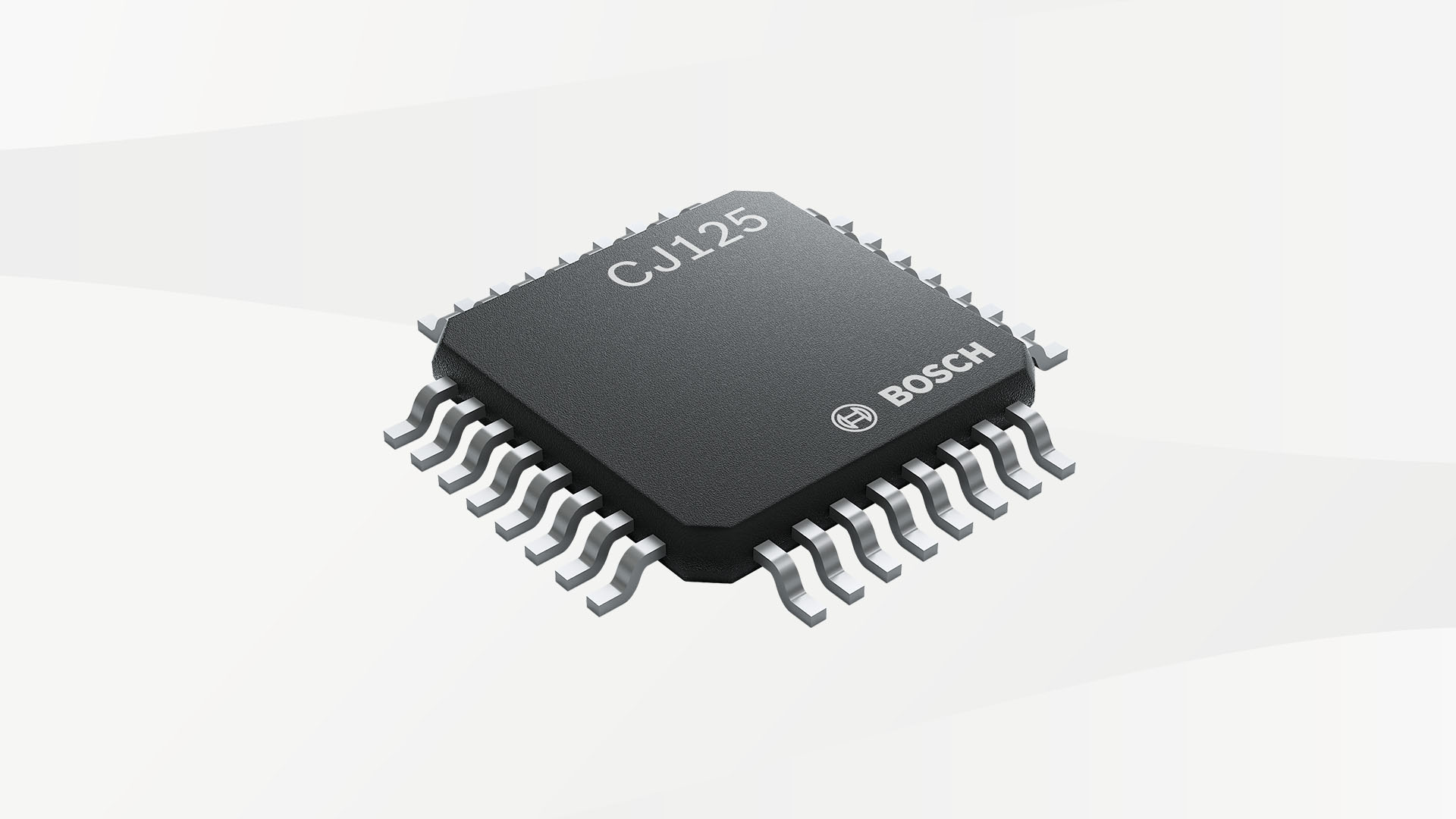

| Part | What Bosch or Niterra names it for | Package and interface in the cited document |
|---|---|---|
| Bosch CJ110 | Bosch LSU, in the Spring 2015 semiconductor catalogue | SOIC16w. Analogue interface. The later catalogues move new designs to the SPI parts. |
| Bosch CJ125 | Current product page: LSU 5.2, LSU 4.9, LSU ADV and LSU 4.2. The Autumn 2016 catalogue lists it as the Bosch LSU interface and marks it recommended for new applications. | SOIC24 and LQFP32 in the 2016 catalogue. The current page specifies LQFP32. SPI. The heater power transistor is external. The chip diagnoses that stage for a short to battery, a short to ground and an open load. |
| Bosch CJ135 | Autumn 2016 catalogue: LSU 4.9, LSU ADV and NTK ZFAS-U2. Current product page adds LSU 5.2, ZFAS-U3 and Denso Plus 5 and Plus 6, and states a regulation range of lambda 0.65 to free air. | TQFP32 with exposed pad. QFN36 is listed on demand in the 2016 catalogue. SPI at 3.3 V or 5 V. Not pin-compatible with the CJ125. |
| Bosch CJ136 | Autumn 2016 catalogue: LSU 4.9, LSU ADV and NTK ZFAS-U2, and an extra UART for cylinder-imbalance measurement. A CJ136 product information sheet says those three sensors can share one ECU hardware build, with the sensor chosen in software. | TQFP32 with exposed pad, or QFN36 on demand, in the 2016 catalogue. SPI. The product information adds a fast digital pump-current line, Ri measurement to 6 kΩ, and downward compatibility with the CJ135 rather than the CJ125. |
| Niterra XCU-UA | ZFAS-U | SPI interface to the vehicle processor, with element-temperature control and open/short detection. Package is not stated on the Niterra page. |
A CJ125 product-information sheet circulated by distributors describes the blocks inside the earlier package: pump-current control, a sense amplifier, a lambda output amplifier, a 450 mV Nernst reference, virtual ground at half the 5 V supply, Ri measurement, and programmable reference pump currents. Source and sink capability on the pump output is given as 10 mA to 30 mA, which covers the LSU sheets’ roughly −9 mA to +6 mA sensor currents. The battery pin in that sheet operates from 9 V to 18 V, with 5 V logic. The pin drawing in that sheet is SOIC24. It does not apply to the LQFP32 part on the current product page.
The LSU 4.2 and LSU 4.9 still carry an individual trim resistor, and the CJ125 gain v is part of the calibration. Selecting v = 17 or v = 8 changes the UA voltage in the table above. The CJ135 product information says that chip operates an LSU 4.9 or an LSU ADV, and that it also meets the joint NTK and Bosch requirement for a ZFAS-U2. The CJ136 product information goes further: LSU 4.9, LSU ADV and ZFAS-U2 can share one ECU hardware build, and the sensor is chosen in software. The LSU ADV sensor sheet, separately, still names the LT4 ADV evaluation unit as the unit that sensor operates with. A CJ125 board set up for an LSU 4.9 remains a different unit from the LT4 ADV named on the LSU ADV sheet.
The current CJ135 page is also the source, on this page, for two further families: NTK ZFAS-U3, and Denso Plus 5 and Plus 6. This page has no Denso characteristic and no ZFAS-U3 characteristic. They are named so that a chip listing is not read as a Bosch-only parts list.
What has to be right before the number is believed
Pressure and placement: AEM's 30-4900 instructions specify a post-turbine location for that gauge and warn that pre-turbine pressure affects accuracy. Other dedicated systems support pre-turbine sensors with pressure compensation; AEM sells a back-pressure kit for a particular four-channel controller. Use the sensor and controller documentation for the actual setup instead of treating either arrangement as universal. AEM 30-4900 instructions; AEM pressure-sensor kit.
The LSU 4.2 installation section is specific and is the one quoted here for the mounting geometry. The sensor has to see a representative sample and stay inside its temperature limits. The electrical connection points upward, at least 10° off horizontal, so liquid does not collect between the housing and the element. The pipe ahead of the sensor should not trap condensate, and the protection tube is oriented so that its front opening is not pointed straight into the oncoming stream. The angle to the stream is aimed at 90°, with the sheet’s allowance of 15° toward the stream and 30° the other way. If condensation cannot be designed out, heater start is delayed until the water is gone.
The ceramic is heated quickly. After that, condensate on the element is a crack. The 4.2 sheet limits heater voltage to 3 V effective while condensation is possible. The 4.9 sheet uses 2 V. Both sheets forbid a 24 V supply unless a converter is used, and both keep the heater under the control unit’s limit rather than across the battery. Light-off guide values are 20 seconds or less on the 4.2 sheet and 10 seconds or less on the 4.9 sheet.
The reference side of an LSU 4.2 needs ambient air. That sheet requires the wires and connector to breathe, and it warns that the pressure-compensation hole in the connector has to stay clear of wax and oil. A sealed or oil-soaked connector shifts the reference and the lambda follows it. On the LSU 4.9 the reference volume is the PTFE hose, and that hose is kept sealed. On the LSU ADV the LT4 ADV description uses an internal oxygen reference. On the NTK ZFAS-U the catalogue and Niterra both say there is no external reference air. The four arrangements are not one instruction.
Innovate and AEM publish their own bung positions for the installations they support. Innovate’s LC-2 manual uses 24 inches downstream and a bung between 9 o’clock and 3 o’clock, with a 500 °C limit at the bung. AEM’s 30-0300 manual uses 18 inches downstream, more than 10° off horizontal, and advises against a fully vertical sensor. Those are the controller manuals. The Bosch temperature and condensation limits are the sensor sheets. Where they differ, the sensor sheet still bounds the ceramic, the hexagon and the connector.
Free-air calibration, when the controller asks for it, is done in air, with the sensor hot and out of the exhaust. Innovate requires it for a new sensor. AEM’s 30-0300 manual prefers the trim-resistor calibration the sensor was given and treats free air as a later check. The display is then set to lambda, or to air-fuel ratio using the stoichiometric ratio of the fuel actually in the tank. AEM states that its AFR face uses 14.65. An AFR scale locked to one gasoline number mis-states an ethanol blend even when the pump current is right. Compare the controller’s lambda with the ECU’s requested lambda on one time base, after the exhaust has had time to reach the sensor.
Choosing among them
| Sensor | Range in the cited sheet | Heater and reference | What the controller must match |
|---|---|---|---|
| Bosch LSU 4.2 | Lambda 0.7 to free air. Zero pump current at lambda 1.009 on the nominal line. | 9 V nominal. About 10 W at 7.5 V in air. Nernst cell 80 Ω. Light-off guide 20 s. External reference air through the connector. | Its own trim resistor. AWS, LA4 or CJ125 are the named examples. RB150 and RB130 pin order differ. |
| Bosch LSU 4.9 | Lambda 0.65 to free air. Motorsport table puts zero pump current at lambda 1.003. | 7.5 V nominal, about 7.5 W. Nernst cell 300 Ω. Light-off guide 10 s. Reference air in the PTFE hose. | Its own trim resistor. CJ125 gain v = 8 or v = 17 changes the output voltage. LT4 is the Motorsport example. Continuous pressure to 2.5 bar. |
| Bosch LSU ADV | Lambda 0.65 to free air. LT4 ADV application window is lambda 0.75 to 5. | Internal oxygen reference in the LT4 ADV description. Five pins, no trim resistor. Hexagon 650 °C. | The evaluation unit in the LT4 ADV. The CJ135 product information also operates an LSU ADV. The CJ136 product information puts LSU 4.9, LSU ADV and ZFAS-U2 on one hardware build and selects the sensor in software. |
| Bosch Mini-LSU 4.9 | Lambda 0.65 to free air on the Motorsport overview. | M16 × 1.5 thread, 34 g. Hexagon listing 700 °C. | A different bung from the M18 sensors. Controller support has to name this part. |
| Bosch LSU 4.7 and LSU 5.1 | Not established here. ETAS calls the 5.1 a lean sensor. | ETAS requires adjustable Nernst and pump limits for the 5.1 and the ADV. | The matching ETAS adapter. A lean sensor does not cover rich mixtures below lambda 1. |
| Bosch LSU 5.2 | Not established here. | Named on the current CJ125 and CJ135 product pages. | A controller whose sensor list includes LSU 5.2. |
| NTK ZFAS-U and ZFAS-U2 | Not established as a manufacturer span on this page. ETAS supports the ZFAS-U2 inside the module’s lambda 0.6 to 16 window. | Own reference, sealed. Five or more wires. Catalogue heater check fails above 30 Ω. | An NTK interface: XCU-UA, CJ135 or CJ136 configured for it, or an ES63x with the ZFAS-U2 cable. Not an LSU selection. |
| NTK ZFAS-U2-SM | Not established here. | ZFAS-U element with the controller and the compensation stored in the connector. | CAN. There is no external pump-current interface to wire as a ZFAS-U2. |
A rich wide-open-throttle target on a petrol engine, commonly inside lambda 0.85 to 0.95 and sometimes richer under boost, needs a sensor whose sheet still measures below lambda 1. LSU 4.2, LSU 4.9 and LSU ADV do. A lean sensor does not. The mixture values themselves are on the mixture page, not a property of the sensor.
Check the controller-to-logger path
A sensor's measurement span, the controller's supported span and the recorded channel's scale are separate specifications. Bosch's interfaces give a useful example:
| Interface | Supported sensors | Published application span |
|---|---|---|
| Lambdatronic LT4 | LSU 4.2, LSU 4.9 and Mini-LSU 4.9; up to four channels. | Lambda 0.75–10.12. |
| Lambdatronic LT4 ADV | LSU ADV; up to four channels. | Lambda 0.75–5. |
Both product pages specify 100 Hz sampling and CAN refresh, analogue lambda outputs, and CAN temperature/diagnostic information. Those rates describe the interfaces, not every downstream ECU or logger. The sensor's wider published span does not automatically become the interface's application range.
For a tuning log, the practical inference is to verify the complete path before adjusting fuel:
- Record the sensor part, controller model, configuration and firmware, and the logger's channel definition.
- For analogue recording, match the configured voltage/lambda transfer and reference-ground arrangement. The sensor evaluation-circuit UA table elsewhere on this page is not a universal finished-controller output scale.
- For CAN, use the matching protocol definition, units and status information. Confirm the actual saved update rate and timestamps rather than assuming 100 Hz because the interface supports it.
- Compare readings only when the controller reports valid operation. Check warm-up and fault information where available, and account for sampling position and transport delay when comparing an external sensor with an ECU trace.
This is a measurement-validation workflow, not evidence that an LT4 or LT4 ADV can replace a particular vehicle ECU's sensor interface. The existing sensor and controller-specific installation limits still apply.
Operational status comes before the lambda number
The LT4 ADV function sheet, pages 8–11, documents a cold-sensor output of lambda 1 before operational temperature is reached. The reviewed LT4 function sheet describes the same behaviour. A flat 1.000 during warm-up can therefore be a placeholder rather than a measured stoichiometric mixture.
| ADV project label | Documented meaning |
|---|---|
| lamyok | Sensor operational. |
| lamytok | Operating temperature reached. |
| lamy_e / lamyh_e | Lambda / heater error. |
| lamyoffset_b | Offset calibration active. |
Here y identifies the sensor channel. Some diagnosis is temperature-gated, so an error flag remaining clear while cold does not prove readiness. The manual also describes heater-on fallback when CAN heater control is selected without CAN commands. Communication loss alone must not be treated as confirmation that the heaters are off. Use the matching firmware's status definitions.
Decode the LT4 CAN values using the protocol
The LT4 function sheet, pages 15–16, gives these default messages. IDs are configurable, so confirm the installed settings:
| Default identifier | Payload interpretation in this document |
|---|---|
| 0x770 | Four unsigned 16-bit lambda values, low byte first; factor 0.000244, zero offset. |
| 0x772 | Sensor temperatures; 5 °C per count with a −40 °C offset. |
| 0x773 | Channel bitfields for lambda/heater errors, operational state and offset calibration. |
For example, bytes 00 10 for one lambda word give 0x1000 = 4096. With the document's stated scale, 4096 × 0.000244 ≈ 0.9994. Reversing byte order produces a different value. This is a decoding exercise, not a sensor calibration result.
The parameter editor expects decimal CAN identifiers: 0x770 is 1904. Keep that input convention distinct from a logger's hexadecimal display. The protocol's representable numeric range is also separate from the valid sensor/controller measurement range above. Confirm the protocol against the installed firmware rather than substituting a product page's nominal resolution as a decoding factor.
Keep calibration files and recorded measurements identifiable
The LT4 quick-start manual, pages 4–9, describes a ModasSport project with separate monitoring and parameter worksheets. It calls for reading controller data before loading its working page for changes. Live measurement and recording are separate operations; recordings can be inspected in WinDarab.
The ADV quick-start manual similarly distinguishes firmware (.HEX) from its variable-description file (.A2L). Retain the identity of both with the configuration and recorded session. These older ModasSport instructions are evidence for their supplied projects, not a statement that every current RaceCon project uses identical screens or file handling.
The practical record should include sensor channel/part, controller and firmware, variable description, analogue conversion or CAN definition, filter settings, saved update rate and a validity trace. Being connected to the configuration tool does not by itself prove that a log was saved.
An analogue scaling check with invented values
Suppose a controller is deliberately configured for lambda 0.50 at 0 V and lambda 1.50 at 5 V, with linear interpolation. The matching conversion is lambda = 0.50 + 0.20 × voltage. Thus 2.50 V represents lambda 1.00. A positive 0.10 V recording offset would add 0.02 to the calculated lambda.
Those endpoints are invented for this arithmetic example; they are not an LT4, AEM or Innovate default. Use the actual controller's configured transfer and grounding instructions. A repeatable offset between a controller reading and the saved analogue channel is a reason to check that measurement path before changing a fuel map.
Logging discussions: offset, scale and operating-point differences
In HP Academy's AEM/Innovate discussion, Andre Simon describes an Innovate-to-legacy-MPVI analogue logging mismatch. He checked fixed 1.0 V and 4.0 V outputs and found that the discrepancy was not identical at both points; additional grounding improved but did not fully resolve it. He reports using serial logging instead, with occasional recognition problems. The exact MPVI revision and scanner build were not established, so this is not evidence of a fault in every current HP Tuners interface.
The useful inference is to test more than one point: a constant offset, gain error and intermittent/noisy signal need different explanations. Matching the display at one mixture does not establish accuracy across the range. Use the controller manufacturer's supported test method and record the input voltage alongside the calculated mixture.
A Hondata forum report describes an Innovate LC-2 with S300/P30JDM logging, with the recorded mixture approximately 0.7–0.8 AFR richer than the gauge at high rpm. Its full software revision, calibration and a verified remedy were not established here. Direct access was blocked; this is an indexed owner report, not an independently inspected trace or a wiring prescription.
A real log can use AFR under a lambda channel name
The inspected BMW log case has channels named Lambda and Lambda Act. displayed in AFR. At viewer time 12.033 s both show 13.10 AFR. Read the units before interpreting the channel name; this is not dimensionless lambda 13.10.
Matching Bosch sensors does not make controller protocols identical
The reviewed AEM 30-0300 manual specifies AEMnet lambda as an unsigned, big-endian word with 0.0001 lambda per count. The Bosch LT4 function sheet specifies low-byte-first words with a different scale. Their identifiers and status layouts also differ.
Constructed example from those published definitions: AEMnet bytes 27 10 represent 10,000 × 0.0001 = lambda 1.0000. Applying the LT4 byte order and factor to those same bytes gives 4,135 × 0.000244 ≈ 1.0089. The wrong definition can therefore produce a plausible-looking value. This is arithmetic, not a captured CAN frame or evidence of a real sensor bias.
Match controller model, firmware and protocol as well as the sensor part. Keep readiness/error states with the recorded mixture; changing the decoding or an analogue offset cannot repair an invalid sensor measurement.
A reported analogue-reference fix with a documented follow-up
In AEm x series wideband datalog issue, the author describes an AEM X-Series feeding an S300 v3 in an OBD2 chassis with a jumper harness. The logged AFR stayed near 19.16 and differed from the gauge by more than five AFR units. On 24 March 2018 the author reports resolving the problem by correcting a bad ground for the brown wire.
This is a first-hand reported outcome from indexed post text; the forum itself was inaccessible at review. The engine, exact X-Series part number, SManager/firmware versions and final grounding point were not established. It supports checking the analogue reference when gauge and logger disagree, rather than assuming an engine mixture fault.
Wire colour must be matched to the controller and connector. In AEM's 30-0300 manual, 12 July 2017, Power/IO white is analogue positive and brown is analogue negative; the manual distinguishes differential-input, shared signal-ground and power-ground connections. In the LC-2 manual, brown is analogue output 2. The AEM case is not an instruction to ground an LC-2 output.
A dual-controller logging case that followed the serial chain
A 23 August 2025 Pelican Parts report describes dual Innovate LC-2 controllers with LogWorks on an older Porsche 911 with a 3.2 Motronic engine. The author posts comparisons at warm idle, in city driving and at 3,000 rpm in fourth gear. These are measurement-system observations on an older ECU, not Porsche MG1 hybrid recordings.
More usefully, the author reports that swapping the controllers' positions in the serial daisy chain moved a plotted anomaly with the chain position, and restoring the order brought it back. The internal cause remained unresolved. The review could read the narrative/captions but could not independently inspect the log images or obtain raw samples; controller firmware and LogWorks build were unspecified.
Record sensor/bank identity, controller identity, chain position and displayed channel separately. Resolve logging anomalies before using bank differences to justify fuel map changes.
Sources
- Bosch, Planar Wide Band Lambda Sensor LSU 4.2, technical product information Y 258 E00 019e, 20 February 2006. Range lambda 0.7 to air; heater 9 V nominal and about 10 W at 7.5 V; cold resistance; 80 Ω Nernst cell; trim resistor; AWS, LA4 and CJ125; AWS and CJ125 voltage formulas; RB150 and RB130 pinout; 24 V supply; nominal pump-current line; 930 °C heater cut-off and 1,030 °C short allowance; light-off guide 20 s; DIN EN 228; installation angle; condensation heater limit 3 V; reference-air path. Accessed 2026-11-12.
- Bosch, Planar Wide Band Lambda Sensor LSU 4.9, technical product information Y 258 E00 015e, 14 June 2005. Range lambda 0.65 to air; heater 7.5 V and about 7.5 W; 300 Ω Nernst cell; 20 µA reference pump current; pin colours; pressure 2.5 bar continuous and 4 bar short-time; exhaust temperature 930 °C; hexagon 600 °C; condensation heater limit 2 V; PTFE reference-air hose; light-off guide 10 s; nominal pump-current line.
- Bosch Motorsport, Lambda Sensor LSU 4.9 data sheet. Lambda 0.65 to air; gasoline, diesel and E85; CJ125 UA table and the note that UA is the evaluation-circuit voltage; accuracy figures; connectors 1928.404.687 and AS607-35PN; orders 0258.017.025 and B261.209.358-03; torque 40 Nm to 60 Nm; LT4 named as a control unit. Product photograph on the LSU 4.9 page.
- Bosch Motorsport, Lambda Sensor LSU ADV data sheet. Lambda 0.65 to air; no trim resistor and five pins; LT4 ADV evaluation unit; hexagon temperature 650 °C operating. Product photograph on the LSU ADV page.
- Bosch Motorsport, Lambda Sensors overview. Mini-LSU 4.9 on M16 × 1.5, and LSU ADV pre-turbo with 980 °C operating exhaust temperature.
- Bosch Motorsport, Lambdatronic LT4 ADV data sheet. Four LSU ADV channels; application lambda 0.75 to 5; CAN and four 0–5 V outputs; internal oxygen reference held at lambda 1.013.
- ETAS ES63x lambda modules. Supports LSU 4.2, LSU 4.7, LSU 4.9, LSU 5.1 described as a lean sensor, LSU ADV-G and NTK ZFAS-U2. Module span lambda 0.6 to 16, with the note that actual values follow the sensor curve. Replaces the LA4. Product rendering of the ES630.1 from that page.
- Innovate Motorsports, LC-2 manual 11-0137C. LSU 4.2 and LSU 4.9, sensor parts 3737 and 3888, default analogue scales, free-air calibration, and the warning that the wrong sensor type can damage the sensor. The MTX-L manual 11-0129B and the multi-sensor guide 11-0144 use the same sensor choice for the MTX-L, LM-2 and SCG-1.
- AEM, 30-0300 X-Series UEGO manual, Bosch LSU 4.9 edition. Sensor 35-2004; display window; 0–5 V formulas; AEMnet; RS-232 compatibility with the 30-4100 and 30-4110. The later AEM/FAE edition of the same manual adds automatic detection of an AEM/FAE sensor or a Bosch LSU 4.9, and states the 14.65 gasoline stoichiometric ratio used on the AFR display.
- Bosch Semiconductors, CJ125 and CJ135. Current sensor lists, packages and the lambda 0.65 to air regulation range stated for each chip. Product renderings from those pages.
- Bosch CJ125 product information, as circulated by TME. Pump-current blocks, 450 mV Nernst reference, 10 mA to 30 mA pump output, 9 V to 18 V battery pin. The pin drawing is SOIC24.
- Bosch, CJ135 lambda probe interface product information. LSU 4.9, LSU ADV and NTK ZFAS-U2; not pin-compatible with the CJ125.
- Bosch Mobility Solutions, Semiconductors and sensors, Autumn 2016. Catalogue rows for CJ125, CJ135 and CJ136. The CJ136 row adds a UART for cylinder-imbalance measurement and names LSU 4.9, LSU ADV and NTK ZFAS-U2. The Spring 2015 edition of the same catalogue is the source for the CJ110 analogue part. The further CJ136 claims, shared hardware with a software sensor choice, the fast digital pump-current line, Ri measurement to 6 kΩ, and compatibility with the CJ135 rather than the CJ125, are from the CJ136 product information reproduced in Bosch’s semiconductor literature.
- NGK Spark Plugs (UK) Ltd, Lambda Sensors Catalogue 2022. NTK ZFAS-U construction, five-wire colours, part-number key, heater check above 30 Ω, thread torque, and the statement that NGK and NTK products in the catalogue are distributed by NGK Spark Plugs (UK) Ltd.
- Niterra, Wide Range Oxygen Sensor. ZFAS-U sealed construction with no external reference air; XCU-UA interface chip; ZFAS-U2-SM with the controller and compensation in the connector and a CAN output. The ZFAS-U2 product text, including activation in about 5 seconds, is also published by dot B as an NGK Spark Plug listing. Accessed 2026-11-12.
- Michael Handrich, wideband zirconia sensor diagram, 2010, CC BY-SA 3.0. Schrauber5, thimble lambda sensor photograph, 2006, public domain.
- Bosch Motorsport: Lambdatronic LT4 and Lambdatronic LT4 ADV. Current manufacturer product specifications for supported sensor types, application ranges, output configuration, diagnostics and interface update rates. Reviewed 17 November 2026.
- Bosch Motorsport: Lambdatronic LT4 Function Sheet, pages 10–11 and 15–17. Warm-up validity, analogue mapping and documented CAN protocol.
- Bosch Motorsport: Lambdatronic LT4 ADV Function Sheet, pages 8–11. Channel status, temperature-dependent diagnosis and heater behaviour.
- Bosch Motorsport: LT4 Quick Start Manual, pages 4–9. ModasSport setup, reading data, measurement and recording.
- Bosch Motorsport: LT4 ADV Quick Start Manual, pages 4–9. Project workflow and firmware/description files. Additional manufacturer manuals reviewed 17 November 2026.
- HP Academy: AEM vs INNOVATE Widebands, Andre Simon's first-hand interface tests and follow-up replies. Hardware/software versions incompletely identified.
- Hondata: AFR differs from the gauge on High RPM, post 96766. Indexed owner report; direct access blocked and no verified fix established.
- AEM: 30-0300 X-Series UEGO manual, document 10-0300, 12 July 2017, AEMnet section. Big-endian lambda encoding; compare the separately cited LT4 protocol. Discussion and protocol examples reviewed 17 November 2026.
- Hondata forum, Db7dud, AEm x series wideband datalog issue, 23–24 March 2018. S300 v3/X-Series discrepancy and author's resolution; indexed post text only, direct forum access unavailable. Engine, exact controller model, firmware and final ground point unverified. Reviewed 2026-11-17.
- Pelican Parts, Discseven, Innovate LC-2 wideband – pros, cons, last straw, 23 August 2025. Dual LC-2/LogWorks on 3.2 Motronic; narrative and log captions reviewed, images/raw samples not independently inspected. Serial-chain-position observation is reported, internal mechanism unresolved. Reviewed 2026-11-17.