The throttle position sensor (TPS) tells the engine control unit (ECU) where the throttle valve is positioned. An incorrect or interrupted signal can cause hesitation, unstable idle, a warning light or reduced power. A fault code identifies a circuit or plausibility problem to investigate; it does not prove the sensor itself is faulty.

Common symptoms and first checks
| What you notice | What to investigate |
|---|---|
| Hesitation, flat spots or jerking when accelerating | Record when it happens and inspect the throttle and pedal signals, connections and wiring. Air leaks, fuel delivery and ignition faults can cause similar symptoms. |
| Unstable idle, stalling or unexpected idle speed | Check throttle movement and deposits, relevant fault codes, intake leaks and the manufacturer’s idle and adaptation procedure. |
| Warning lamp or reduced-power mode | Record all codes and freeze-frame data. Check the specified sensor circuits, correlation and actuator operation before replacing parts. |
| Poor response to the accelerator | Compare pedal position, commanded throttle and measured throttle where supported. Investigate the pedal, throttle actuator, power supplies and wiring as indicated. |
| Fault appears after cleaning, battery work or replacement | Check connectors, correct part and installation; follow any vehicle-specific initialisation or throttle adaptation procedure. |
Symptoms vary by engine and system; a signal can be faulty without causing every symptom. A HELLA Ford Focus example describes reduced power and plausible sensor, connector and throttle-body causes for specific vehicles.
Throttle sensor or accelerator pedal sensor?
On a cable-operated throttle, the accelerator moves the throttle through a mechanical linkage and the TPS reports throttle position. Some older systems use an idle/full-throttle switch rather than a continuously variable sensor. On an electronic throttle, the accelerator pedal position sensor (APP) reports driver demand; the ECU controls a motorised throttle and reads throttle position feedback. Pedal demand and throttle angle are related, but they are not necessarily equal: the ECU may alter throttle opening for idle, traction control, emissions or protection.
Many electronic systems have multiple sensor tracks or channels for plausibility checking. Their directions, scaling, voltage ranges and expected relationships depend on the vehicle; two traces do not always run in opposite directions. Some throttle position sensors are integrated into the throttle body, while others are serviceable separately. Check the exact vehicle information and available parts.
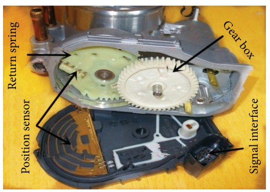
What commonly goes wrong
- Worn sensor track or internal failure: an intermittent dropout can occur at a particular throttle angle; non-contact sensor designs fail differently.
- Wiring or connector faults: damaged insulation, corrosion, loose terminals, oil or water ingress, a poor ground, or a short/open circuit can distort feedback.
- Reference supply: a shared reference or ground fault may affect several sensors at once. Use the wiring diagram to identify shared circuits.
- Throttle body or actuator: deposits, mechanical binding, a motor or drive fault, or air leaks can cause an actual position to differ from the ECU’s request.
- Pedal circuit: an APP signal or wiring problem may cause reduced response even if throttle-position feedback is sound.
- Incorrect fitting or adaptation: an incorrect part, connector problem, disturbed gasket, or incomplete required initialisation can cause trouble after repair.
Fault codes: start with the complete definition
P0120–P0124 commonly refer to throttle/pedal position sensor or switch A circuit faults; P0220–P0224 commonly concern circuit B. P2135 can indicate a throttle/pedal position sensor or switch A/B voltage correlation issue. P2101, P2119 and P2176 are examples of throttle actuator or learned-position codes. Definitions and diagnostic conditions vary by manufacturer: identify whether the affected circuit is at the throttle body or pedal and use the manufacturer’s fault tree. See the HELLA OBD code list.
Practical diagnostic sequence
- Record the complaint. Note idle, acceleration, heat, vibration and recent work. Save all codes and freeze-frame data, including other reference-voltage, pedal, throttle actuator or airflow faults.
- Check the basics. Confirm battery condition and relevant power and earth connections. Examine the intake duct, throttle connector and wiring for damage, loose pins, moisture and contamination.
- Identify the system. Obtain the correct wiring diagram, sensor type, circuit identification, specifications and test conditions. Identify whether a sensor, switch, throttle body or pedal assembly is actually implicated.
- Review live data. With the manufacturer’s safe procedure, observe both APP channels and throttle feedback channels as applicable, plus desired and actual throttle position. Look for implausible changes or disagreement, but remember scan-tool values may be filtered, scaled or updated too slowly to show a brief dropout.
- Measure the circuits. Check specified sensor supply and ground under the stated conditions. A healthy reference at the ECU may not prove it reaches the sensor. Use approved back-probes and avoid spreading terminals or shorting adjacent pins.
- Capture the signal. Use a scope or suitable meter to monitor the specified signal and, where appropriate, both channels together through the range permitted by the manufacturer. A potentiometer’s signal should change smoothly as its position changes; sudden dropouts or spikes merit investigation. Compare actual voltages and channel relationships with the correct vehicle data, not a universal number.
- Separate sensor from wiring and actuator faults. Compare signal at the sensor and ECU when indicated; inspect the harness under the conditions that reproduce the complaint. If feedback accurately follows the plate but the plate does not reach its request, inspect the actuator, supply and mechanics using the prescribed tests.
- Repair, initialise and verify. Repair the confirmed fault, perform specified adaptation if required, then repeat the original operating conditions. Recheck codes and live data; perform a road test only when the vehicle is safe to drive.
Pico’s throttle potentiometer test explains waveform testing, while its accelerator pedal test covers a separate pedal circuit. Follow the vehicle manufacturer’s instructions if they differ.
Reading the signal without guessing
For a conventional potentiometer, the output changes with throttle angle and a scope can reveal an intermittent worn section that a slow scan-tool display misses. Some designs use contactless sensors or switched signals; an older idle/full-throttle switch will not produce the same gradual sweep. Identify the sensor before choosing a test. A steady reading alone does not prove the plate is moving correctly, and a fault in a shared supply can make a good sensor report an incorrect value.
Compare both feedback channels against the manufacturer’s specified range and relationship at the same operating point. Do not assume that the pedal and throttle percentages should match, or that every channel must start at zero or finish at 100%. Compare requested and actual plate position only using the specified test conditions; the ECU can intentionally limit movement.

Safe cleaning, replacement and final checks
An electronic throttle can move unexpectedly when powered. Keep fingers and tools clear of the plate; switch off and isolate the system as the manufacturer specifies before inspection or cleaning. Do not force a motorised plate, energise the actuator directly or spray cleaner into electronics unless the vehicle procedure explicitly permits it. Use the specified cleaner and method, and replace seals where required.
Fit the correct sensor or complete throttle assembly as specified. Some vehicles require an idle or throttle position relearn after cleaning, replacement or power interruption; others have different procedures. Clear codes at the appropriate stage, repeat the test, check for intake leaks and verify idle and response. A returning code requires a fresh diagnosis rather than repeated calibration.
Related diagnostic guides
- Exhaust gas temperature sensor faults — exhaust temperature, wiring and regeneration checks.
- Intake air temperature sensor faults — air temperature, wiring and heat-soak checks.
- Knock sensor faults — knock sensing, wiring and combustion checks.
- Accelerator pedal position sensor faults — pedal input and acceleration response checks.
- Camshaft position sensor faults
- Crankshaft position sensor faults
- Coolant temperature sensor faults
- Oxygen sensor faults
- MAP sensor faults
- MAF sensor faults
- Fuel pressure sensor faults
- Fuel pump faults
- Injector faults
- DPF faults
- EGR faults
- Turbo diagnostics
- Boost leaks
For further system background see electronic throttle control and throttle body.