An exhaust gas temperature sensor (EGT or EGTS) measures temperature at a particular point in the exhaust. The engine control unit (ECU) may use the reading to protect components, control fuelling and manage exhaust aftertreatment, including diesel particulate filter (DPF) regeneration. A temperature fault can come from the sensor or wiring, but genuinely excessive exhaust temperature and other exhaust-system problems need their own investigation.
Symptoms and first checks
| Observation | What to investigate |
|---|---|
| Engine, DPF or glow-plug warning lamp | Record all fault codes and freeze-frame data. Identify the affected exhaust sensor and circuit using the vehicle information. |
| Reduced performance or restricted operation | Check for EGT sensor faults and ECU protective strategies; boost, fuel, exhaust restriction and other faults can produce similar symptoms. |
| Repeated, long or unsuccessful DPF regenerations | Review EGT readings, regeneration status, pressure sensing and other conditions. Do not assume the filter or temperature sensor is defective without testing. |
| Implausible fixed, very high or very low value | Check for a substituted value, an open or short circuit, damaged sensor or wiring, and the correct live-data parameter. |
| Fault after exhaust, turbo or DPF work | Inspect connectors, wiring routes, sensor locations and correct part numbers. Nearby sensors can look similar but use different calibrations. |
Symptoms and fallback behaviour depend on the vehicle. HELLA lists warning lamps, altered regeneration and reduced performance among possible effects. An EGT circuit code does not on its own prove that the sensing probe has failed.
Where are EGT sensors fitted?
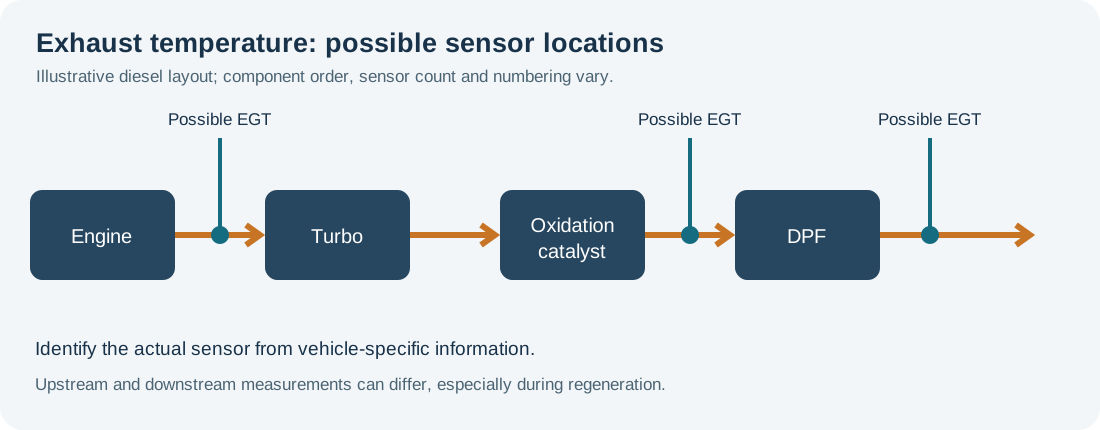
Sensors can be fitted before or after a turbocharger, catalytic converter or particulate filter, and at other aftertreatment locations. A vehicle may have several. The ECU uses each reading for its particular location; an upstream reading need not equal a downstream reading, especially as operating conditions and regeneration change. Identify sensor number and bank using the exact engine and exhaust layout rather than guessing from position or connector colour.
EGT sensors measure temperature. Oxygen sensors measure oxygen-related exhaust conditions, while a DPF differential-pressure sensor measures a pressure difference through pipes. They have different jobs even when mounted close together. NTK’s EGT overview describes the range of possible locations.
Sensor types: PTC and NTC
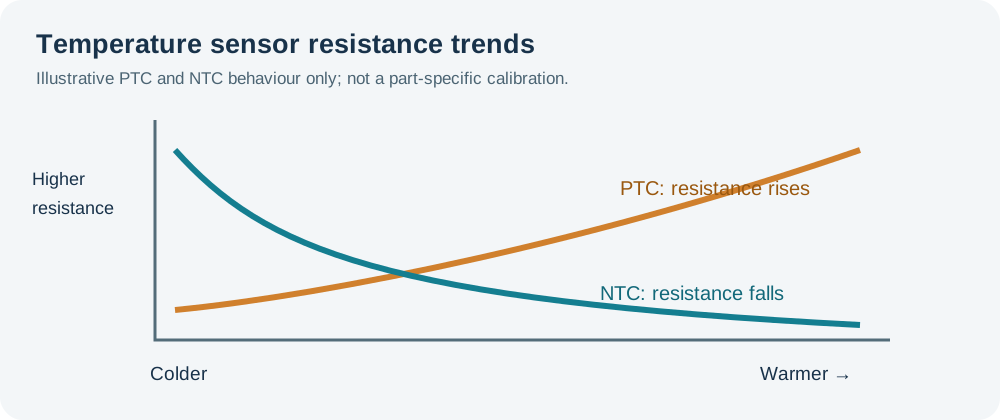
Many EGT sensors use a temperature-sensitive resistor. A positive-temperature-coefficient (PTC) element generally increases in resistance as it warms; a negative-temperature-coefficient (NTC) element decreases. Sensor construction, ECU input circuits and calibration differ, and other high-temperature sensing designs exist. Do not apply an IAT sensor’s resistance curve, a universal voltage, or another part number’s specification to an EGT sensor.
Common causes
- Wiring and connector: heat damage, chafing, corrosion, loose terminals or a broken conductor from vibration can interrupt the signal.
- Probe damage: excessive temperature, contamination, internal failure or physical damage can affect response. The cause of overheating also needs diagnosis.
- Installation: incorrect sensor, damaged threads, poor harness routing or incorrectly connected nearby sensors can produce a recurring fault.
- Actual exhaust conditions: a fuelling or combustion problem, exhaust restriction, aftertreatment fault or regeneration event may result in a genuinely high temperature.
- Control-unit substitution: the ECU may display a fallback value when a circuit is implausible; the displayed value is not necessarily the physical exhaust temperature.
Fault codes
Generic P0544–P0546 commonly describe the bank 1 sensor 1 EGT circuit, low and high conditions; P2031–P2033 commonly describe the bank 1 sensor 2 circuit, low and high conditions. Other codes apply to different banks, sensors or temperature plausibility. Use the full manufacturer-specific definition and wiring diagram to locate the affected sensor. A high or low circuit code identifies an electrical input condition; it does not alone establish the actual exhaust temperature. See the HELLA OBD code list.
Practical diagnostic sequence
- Record the complaint. Save all codes and freeze-frame information. Note whether the fault occurred during starting, sustained load, regeneration or after exhaust work, and check relevant service information.
- Identify the correct sensor. Locate the bank, sensor number, connector, exhaust position, signal type and part number from vehicle-specific data. Distinguish measured values from calculated or substituted values.
- Make the system safe. Exhaust components can remain extremely hot after shutdown or regeneration. Allow them to cool, secure the vehicle and use suitable protection and the manufacturer’s workshop procedure.
- Inspect the harness and mounting. Look for heat damage, stretched leads, missing clips, chafing, corrosion and water ingress. Do not pull on the sensor cable or disturb a seized probe unnecessarily.
- Compare cold readings. After the vehicle has cooled sufficiently and components have stabilised, compare the relevant EGT values with a suitable ambient reference and other sensors as specified. Different locations and residual heat can produce differences; an agreement at one temperature does not prove accuracy throughout the range.
- Check the circuit. Follow the vehicle diagram and prescribed isolation procedure to test the sensor connector, wiring, signal and ground or reference as applicable. Check continuity and shorts only with the circuit isolated as directed.
- Test the identified sensor. If specified, measure disconnected resistance at a known sensor temperature and compare with the exact part’s PTC or NTC curve. A single plausible resistance does not prove response at exhaust operating temperatures. Never use an ohmmeter on a powered circuit or unidentified control-module pins.
- Investigate real temperature and aftertreatment. Review temperatures, regeneration state, fuel and air-system data and relevant pressure readings under manufacturer-specified conditions. Use appropriate high-temperature measurement equipment and an approved method if an independent comparison is needed.
- Repair and verify. Correct wiring, sensor or underlying engine faults, follow any specified reset or adaptation, then repeat the original conditions safely and check for returning codes.
Do not deliberately create excessive exhaust temperatures to test a sensor. Do not initiate a forced regeneration simply to clear a warning; first diagnose the cause, confirm the procedure’s prerequisites and carry it out only with suitable equipment and fire precautions. Keep clear of the hot exhaust and provide adequate ventilation.
DPF regeneration and temperature readings
During regeneration the ECU manages operating conditions to raise filter temperature and burn soot. The observed temperatures depend on sensor position, operating state and aftertreatment design. A failed or implausible EGT input can affect regeneration or trigger a fallback strategy, while genuinely abnormal temperatures can result from other engine or exhaust faults. Check the original sensor fault alongside DPF differential pressure, soot estimates and the manufacturer’s regeneration conditions. See common DPF faults.
Never assume that a high sensor value during regeneration means an over-temperature fault, or that a plausible scan-tool value proves the sensor is accurate. Compare against the manufacturer’s limits, operating conditions and a suitable independent reference when indicated.
Replacing an EGT sensor
Use the correct part for the exact location and follow the manufacturer’s removal and fitting procedure. Exhaust threads may seize; avoid damaging the exhaust housing or twisting the wiring. Observe the specified torque and seal or thread treatment, and do not add compounds where the sensor or vehicle instructions prohibit them. Route the lead through its original clips clear of heat and moving parts.
After repair, confirm that the relevant reading responds plausibly, check the exhaust and connections, clear codes when appropriate and verify the original complaint. If overheating or failed regeneration remains, investigate its underlying cause rather than repeatedly replacing sensors.
Related diagnostic guides
- Intake air temperature sensor faults
- Knock sensor faults
- Accelerator pedal position sensor faults
- Throttle position sensor faults
- Camshaft position sensor faults
- Crankshaft position sensor faults
- Coolant temperature sensor faults
- Oxygen sensor faults
- MAP sensor faults
- MAF sensor faults
- Fuel pressure sensor faults
- Fuel pump faults
- Injector faults
- DPF faults
- EGR faults
- Turbo diagnostics
- Boost leaks
- Intake air temperature sensors and heat soak