Removed text is struck through; added text is highlighted.
An engine dynamometer tests an engine mounted in a test cell, with its output shaft coupled to a controlled load. The measurement boundary is at the coupling or absorber, subject to the location of the torque sensor and any losses between engine and sensor. It excludes a vehicle's gearbox, differential and tyres, but the reported result still depends on engine accessories and test configuration.
An engine test-cell arrangement using a reaction torque arm and separate speed pickup. Original schematic created for Tuning Wiki; based on the technical sources cited in this article.
Principle of operation
The engine turns the absorber through a suitable guarded coupling. An absorber resists the rotation. A reaction torque arm and load cell or an inline torque transducer measures torque; a speed pickup measures shaft speed. Mechanical power is P = Tω, with torque in newton metres and angular speed in radians per second. Equivalently, power in kW is torque in N·m multiplied by rpm and divided by approximately 9549. SuperFlow: engine and dynamometer inertia.
Water brakes dissipate energy by fluid circulation and heating; eddy-current brakes dissipate it electromagnetically. Electric AC or DC machines can absorb power, and a suitably configured machine can also motor the engine. A regenerative drive can return some absorbed electrical energy to the supply, whereas other installations use a load bank. Capability, limits and cooling depend on the particular machine. SuperFlow AC engine dynamometer.
Steady state and sweeps
In steady-state testing the controller adjusts absorber load to hold a selected engine speed while the operator sets throttle and records stable torque, temperatures, fuel, air and other channels. This permits controlled mapping at selected operating points. In a sweep the engine accelerates through the range at a chosen or resulting rate. Some torque accelerates the engine and coupling inertia rather than reaching the absorber, so a sweep needs an appropriate inertia correction if the desired result includes that component. The correction depends on the actual rotating assembly and rate of acceleration; uncorrected transient and steady values are not automatically identical. SuperFlow inertia discussion.
Test-cell installation
The engine needs a secure stand, correctly aligned and rated coupling and guards, cooling and coolant control, oil, fuel delivery, intake supply, exhaust extraction and control/monitoring connections. Fans and cell ventilation must suit the engine and absorber. The SuperFlow SF-Powermark system illustrates a direct engine coupling, controlled engine cooling and water-brake load control. Follow the specific test-cell procedures and limits.
What a result means
Record the torque measurement location, engine speed, fuel, temperatures, atmospheric conditions, correction standard, sweep rate and accessories fitted. An output with a test exhaust, pump and intake may differ from the same engine installed in a vehicle. Engine-dyno output is not wheel power; drivetrain losses and tyres account for part of the difference, but no single fixed percentage applies to every vehicle.
Engine dyno loading and measurement arrangementsAbsorberHow it works on an engine standWhat to specify
Water brakeRotor and stator transfer shaft work into moving water and heat. A controlled water valve changes the available load.Torque–speed curve, clean water supply, pressure, flow and heat rejection. Inlet and outlet-valve systems are not identical. Froude F-series.
Eddy-current brakeAn excited magnetic field and relative motion produce currents whose reaction resists rotation; braking heat is removed by air or water cooling.Field power, speed range, low-speed load capability and continuous thermal rating. A water-cooled eddy brake is still an electromagnetic absorber.
Electric motor/generatorA controlled electric machine can absorb power; a suitable four-quadrant system can also motor the engine. Energy may be sent to a load bank, shared or returned to the supply according to the drive.Motoring and absorption envelope, inverter, power-system interface, protection and cooling. A controller alone cannot add motoring to an absorption-only brake. SuperFlow AC systems.A reaction load cell measures force on the absorber housing through a known arm; an in-line transducer measures torque at its own location in the shaft. Those are different measurement locations. Coupling losses and accelerated inertia can affect how either relates to crankshaft torque. Use the equipment's calibration and analysis method and state precisely where the measurement was made. See eddy-current dynos, water and hydraulic brakes, and electric dynos.Instrumentation and engine configurationAlongside calibrated torque and shaft speed, an engine test cell can log manifold pressure, inlet and exhaust temperatures, oil pressure and temperature, fuel flow, lambda or air–fuel ratio, coolant conditions and ambient pressure and temperature. Sensors and software channels are options on many systems; the SF-902S description provides an example of test-cell instrumentation and optional actuators.Document the engine's intake, exhaust, ECU calibration, fuel, lubrication and cooling hardware and which accessories are fitted or driven. Gross, net, corrected and uncorrected results describe different test conditions or calculations; quote the exact procedure and standard instead of adding a generic correction to another test. Compare like-for-like engine setups and record inlet and thermal conditions with each run. Correction does not make unlike accessory or exhaust configurations identical.At a particular shaft and instant, power (kW) = torque (N·m) × speed (rpm) ÷ 9,549.3. For a representative steady point of 400 N·m at 3,000 rpm this is approximately 125.7 kW. During an accelerating test, additional torque accelerates the engine, coupling and dyno rotating parts. Whether and how this is compensated depends on the measured boundary, effective inertia and the software's method. SuperFlow explains an example of determining total engine and dynamometer inertia.Test-cell operation and durabilityA typical development sequence includes a baseline with documented settings, steady operating points or a controlled sweep, and a repeat test after an identified change. Warm-up and stabilisation matter for oil, coolant, inlet and absorber conditions. Automated endurance or emissions cycles require suitable throttle actuation, safety monitoring and cell services; do not assume a manual dyno installation can run them unattended.Choose stands, adapters, couplings, shaft guards, cooling and extraction for the engine and the cell. Confirm oil and fuel supply, vibration, absorber water or electrical supply, ventilation, fire protection and emergency procedures with the equipment supplier. A high peak power rating does not guarantee that the absorber can dissipate the same power continuously at every RPM. See dynamometer test setup and safety.Engine-dyno makes and modelsThese examples are documented system families, not a ranking. Rated peak torque, speed and power do not necessarily occur together; consult the specific torque–speed curve and duty limits.Manufacturer and modelAbsorber and application
SuperFlow SF-902SWater-brake engine dyno with an outlet-control valve, test-cell acquisition and a docking arrangement. Manufacturer information; operator manual.
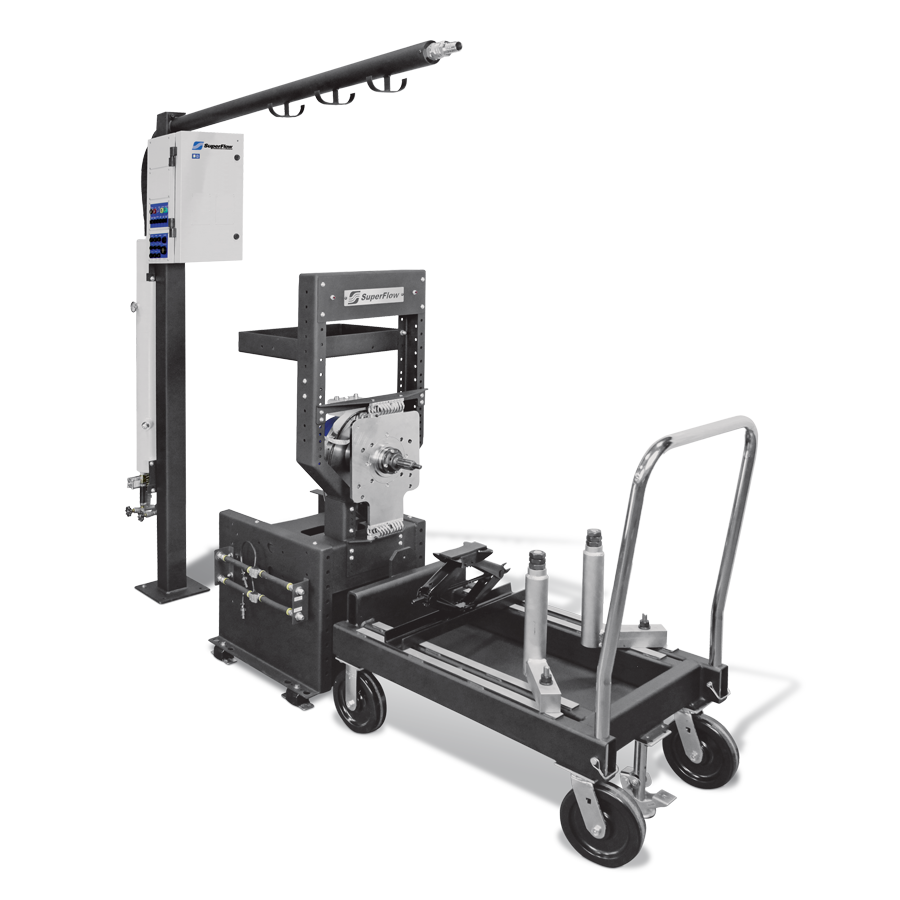
SuperFlow SF-PowermarkWater-brake engine test system; manufacturer describes inlet and outlet load valves and an engine docking cart. Product page.
SuperFlow AC-SeriesElectric-machine engine dynos with absorption and motoring options; energy-handling equipment depends on the installation. AC series.
Froude F24 / F249F-series hydraulic water-brake variants with different published operating envelopes; load is controlled through the specified water valve. F-series specification.
Power Test W-ST / 35XWater-brake families for larger engine and industrial applications; sizing, cooling and operating envelope differ by model. Water-brake range.SuperFlow SF-902S water-brake engine dynamometer. Image: SuperFlow, used with permission.Froude F24 hydraulic water-brake dynamometer. Image: Froude, used with permission.Manufacturer and supplier examplesSuperFlow’s SF-Powermark is a water-brake engine test system with a compliant coupling, docking cart and inlet/outlet valve control. Advanced Dyno Solutions lists engine-dyno equipment among its offered services and equipment; individual machines and availability vary.SF-Powermark engine dynamometer and cart. Image: SuperFlow; used by permission.
See also: Dynamometers overview · Rolling roads · Engine dynamometers · Hub dynamometers · On-car and portable systems · Inertia dynamometers.
Related company profilesFroude · SuperFlow · Power Test · HORIBA.Further examples include AVL active engine and e-drive testbeds, Dyno One motor and brake test systems and Taylor Dyno water-brake systems; each installation has its own operating envelope and control equipment.For examples of complete engine dynamometers and their controls, see SAJ Test Plant water-brake and eddy-current families.
Rendered revisions
Open each version to inspect formatting, tables and photographs.
Revision 2: Engine dynamometers
An engine dynamometer tests an engine mounted in a test cell, with its output shaft coupled to a controlled load. The measurement boundary is at the coupling or absorber, subject to the location of the torque sensor and any losses between engine and sensor. It excludes a vehicle's gearbox, differential and tyres, but the reported result still depends on engine accessories and test configuration.
Principle of operation
The engine turns the absorber through a suitable guarded coupling. An absorber resists the rotation. A reaction torque arm and load cell or an inline torque transducer measures torque; a speed pickup measures shaft speed. Mechanical power is P = Tω, with torque in newton metres and angular speed in radians per second. Equivalently, power in kW is torque in N·m multiplied by rpm and divided by approximately 9549. SuperFlow: engine and dynamometer inertia.
Water brakes dissipate energy by fluid circulation and heating; eddy-current brakes dissipate it electromagnetically. Electric AC or DC machines can absorb power, and a suitably configured machine can also motor the engine. A regenerative drive can return some absorbed electrical energy to the supply, whereas other installations use a load bank. Capability, limits and cooling depend on the particular machine. SuperFlow AC engine dynamometer.
Steady state and sweeps
In steady-state testing the controller adjusts absorber load to hold a selected engine speed while the operator sets throttle and records stable torque, temperatures, fuel, air and other channels. This permits controlled mapping at selected operating points. In a sweep the engine accelerates through the range at a chosen or resulting rate. Some torque accelerates the engine and coupling inertia rather than reaching the absorber, so a sweep needs an appropriate inertia correction if the desired result includes that component. The correction depends on the actual rotating assembly and rate of acceleration; uncorrected transient and steady values are not automatically identical. SuperFlow inertia discussion.
Test-cell installation
The engine needs a secure stand, correctly aligned and rated coupling and guards, cooling and coolant control, oil, fuel delivery, intake supply, exhaust extraction and control/monitoring connections. Fans and cell ventilation must suit the engine and absorber. The SuperFlow SF-Powermark system illustrates a direct engine coupling, controlled engine cooling and water-brake load control. Follow the specific test-cell procedures and limits.
What a result means
Record the torque measurement location, engine speed, fuel, temperatures, atmospheric conditions, correction standard, sweep rate and accessories fitted. An output with a test exhaust, pump and intake may differ from the same engine installed in a vehicle. Engine-dyno output is not wheel power; drivetrain losses and tyres account for part of the difference, but no single fixed percentage applies to every vehicle.
An engine dynamometer tests an engine mounted in a test cell, with its output shaft coupled to a controlled load. The measurement boundary is at the coupling or absorber, subject to the location of the torque sensor and any losses between engine and sensor. It excludes a vehicle's gearbox, differential and tyres, but the reported result still depends on engine accessories and test configuration.
An engine test-cell arrangement using a reaction torque arm and separate speed pickup. Original schematic created for Tuning Wiki; based on the technical sources cited in this article.
Principle of operation
The engine turns the absorber through a suitable guarded coupling. An absorber resists the rotation. A reaction torque arm and load cell or an inline torque transducer measures torque; a speed pickup measures shaft speed. Mechanical power is P = Tω, with torque in newton metres and angular speed in radians per second. Equivalently, power in kW is torque in N·m multiplied by rpm and divided by approximately 9549. SuperFlow: engine and dynamometer inertia.
Water brakes dissipate energy by fluid circulation and heating; eddy-current brakes dissipate it electromagnetically. Electric AC or DC machines can absorb power, and a suitably configured machine can also motor the engine. A regenerative drive can return some absorbed electrical energy to the supply, whereas other installations use a load bank. Capability, limits and cooling depend on the particular machine. SuperFlow AC engine dynamometer.
Steady state and sweeps
In steady-state testing the controller adjusts absorber load to hold a selected engine speed while the operator sets throttle and records stable torque, temperatures, fuel, air and other channels. This permits controlled mapping at selected operating points. In a sweep the engine accelerates through the range at a chosen or resulting rate. Some torque accelerates the engine and coupling inertia rather than reaching the absorber, so a sweep needs an appropriate inertia correction if the desired result includes that component. The correction depends on the actual rotating assembly and rate of acceleration; uncorrected transient and steady values are not automatically identical. SuperFlow inertia discussion.
Test-cell installation
The engine needs a secure stand, correctly aligned and rated coupling and guards, cooling and coolant control, oil, fuel delivery, intake supply, exhaust extraction and control/monitoring connections. Fans and cell ventilation must suit the engine and absorber. The SuperFlow SF-Powermark system illustrates a direct engine coupling, controlled engine cooling and water-brake load control. Follow the specific test-cell procedures and limits.
What a result means
Record the torque measurement location, engine speed, fuel, temperatures, atmospheric conditions, correction standard, sweep rate and accessories fitted. An output with a test exhaust, pump and intake may differ from the same engine installed in a vehicle. Engine-dyno output is not wheel power; drivetrain losses and tyres account for part of the difference, but no single fixed percentage applies to every vehicle.
Engine dyno loading and measurement arrangements
Absorber
How it works on an engine stand
What to specify
Water brake
Rotor and stator transfer shaft work into moving water and heat. A controlled water valve changes the available load.
Torque–speed curve, clean water supply, pressure, flow and heat rejection. Inlet and outlet-valve systems are not identical. Froude F-series.
Eddy-current brake
An excited magnetic field and relative motion produce currents whose reaction resists rotation; braking heat is removed by air or water cooling.
Field power, speed range, low-speed load capability and continuous thermal rating. A water-cooled eddy brake is still an electromagnetic absorber.
Electric motor/generator
A controlled electric machine can absorb power; a suitable four-quadrant system can also motor the engine. Energy may be sent to a load bank, shared or returned to the supply according to the drive.
Motoring and absorption envelope, inverter, power-system interface, protection and cooling. A controller alone cannot add motoring to an absorption-only brake. SuperFlow AC systems.
A reaction load cell measures force on the absorber housing through a known arm; an in-line transducer measures torque at its own location in the shaft. Those are different measurement locations. Coupling losses and accelerated inertia can affect how either relates to crankshaft torque. Use the equipment's calibration and analysis method and state precisely where the measurement was made. See eddy-current dynos, water and hydraulic brakes, and electric dynos.
Instrumentation and engine configuration
Alongside calibrated torque and shaft speed, an engine test cell can log manifold pressure, inlet and exhaust temperatures, oil pressure and temperature, fuel flow, lambda or air–fuel ratio, coolant conditions and ambient pressure and temperature. Sensors and software channels are options on many systems; the SF-902S description provides an example of test-cell instrumentation and optional actuators.
Document the engine's intake, exhaust, ECU calibration, fuel, lubrication and cooling hardware and which accessories are fitted or driven. Gross, net, corrected and uncorrected results describe different test conditions or calculations; quote the exact procedure and standard instead of adding a generic correction to another test. Compare like-for-like engine setups and record inlet and thermal conditions with each run. Correction does not make unlike accessory or exhaust configurations identical.
At a particular shaft and instant, power (kW) = torque (N·m) × speed (rpm) ÷ 9,549.3. For a representative steady point of 400 N·m at 3,000 rpm this is approximately 125.7 kW. During an accelerating test, additional torque accelerates the engine, coupling and dyno rotating parts. Whether and how this is compensated depends on the measured boundary, effective inertia and the software's method. SuperFlow explains an example of determining total engine and dynamometer inertia.
Test-cell operation and durability
A typical development sequence includes a baseline with documented settings, steady operating points or a controlled sweep, and a repeat test after an identified change. Warm-up and stabilisation matter for oil, coolant, inlet and absorber conditions. Automated endurance or emissions cycles require suitable throttle actuation, safety monitoring and cell services; do not assume a manual dyno installation can run them unattended.
Choose stands, adapters, couplings, shaft guards, cooling and extraction for the engine and the cell. Confirm oil and fuel supply, vibration, absorber water or electrical supply, ventilation, fire protection and emergency procedures with the equipment supplier. A high peak power rating does not guarantee that the absorber can dissipate the same power continuously at every RPM. See dynamometer test setup and safety.
Engine-dyno makes and models
These examples are documented system families, not a ranking. Rated peak torque, speed and power do not necessarily occur together; consult the specific torque–speed curve and duty limits.
F-series hydraulic water-brake variants with different published operating envelopes; load is controlled through the specified water valve. F-series specification.
Water-brake families for larger engine and industrial applications; sizing, cooling and operating envelope differ by model. Water-brake range.
SuperFlow SF-902S water-brake engine dynamometer. Image: SuperFlow, used with permission.Froude F24 hydraulic water-brake dynamometer. Image: Froude, used with permission.
Manufacturer and supplier examples
SuperFlow’s SF-Powermark is a water-brake engine test system with a compliant coupling, docking cart and inlet/outlet valve control. Advanced Dyno Solutions lists engine-dyno equipment among its offered services and equipment; individual machines and availability vary.
SF-Powermark engine dynamometer and cart. Image: SuperFlow; used by permission.