AiM produces motorsport lap timers, standalone data loggers and combined display/loggers. These can record vehicle performance for review after a run, but the available channels depend on the exact device, wiring, ECU protocol, sensors and configuration. This guide compares examples used in cars; check the current specification and vehicle-specific connection guide before ordering or wiring a system.
Individual model pages
Detailed specifications, model-specific connector assignments, wiring and manufacturer photographs:
Choose the format
- Solo 2 DL: a compact GPS lap timer and logger with its own display, adding ECU connection to the standard Solo 2. Useful when lap timing and selected ECU data are the priority.
- EVO6: a standalone logger without an integrated dashboard display, suited to a more permanent sensor and ECU installation.
- MXG 1.3: a 7-inch colour dash with integrated data logging, combining driver display and acquisition in one unit.
Product pictures are available from AiM's official product photography gallery. Select MXG 1.3, EVO6/EVO6L or Solo 2/Solo 2 DL for the manufacturer's photographs.
Solo 2 DL
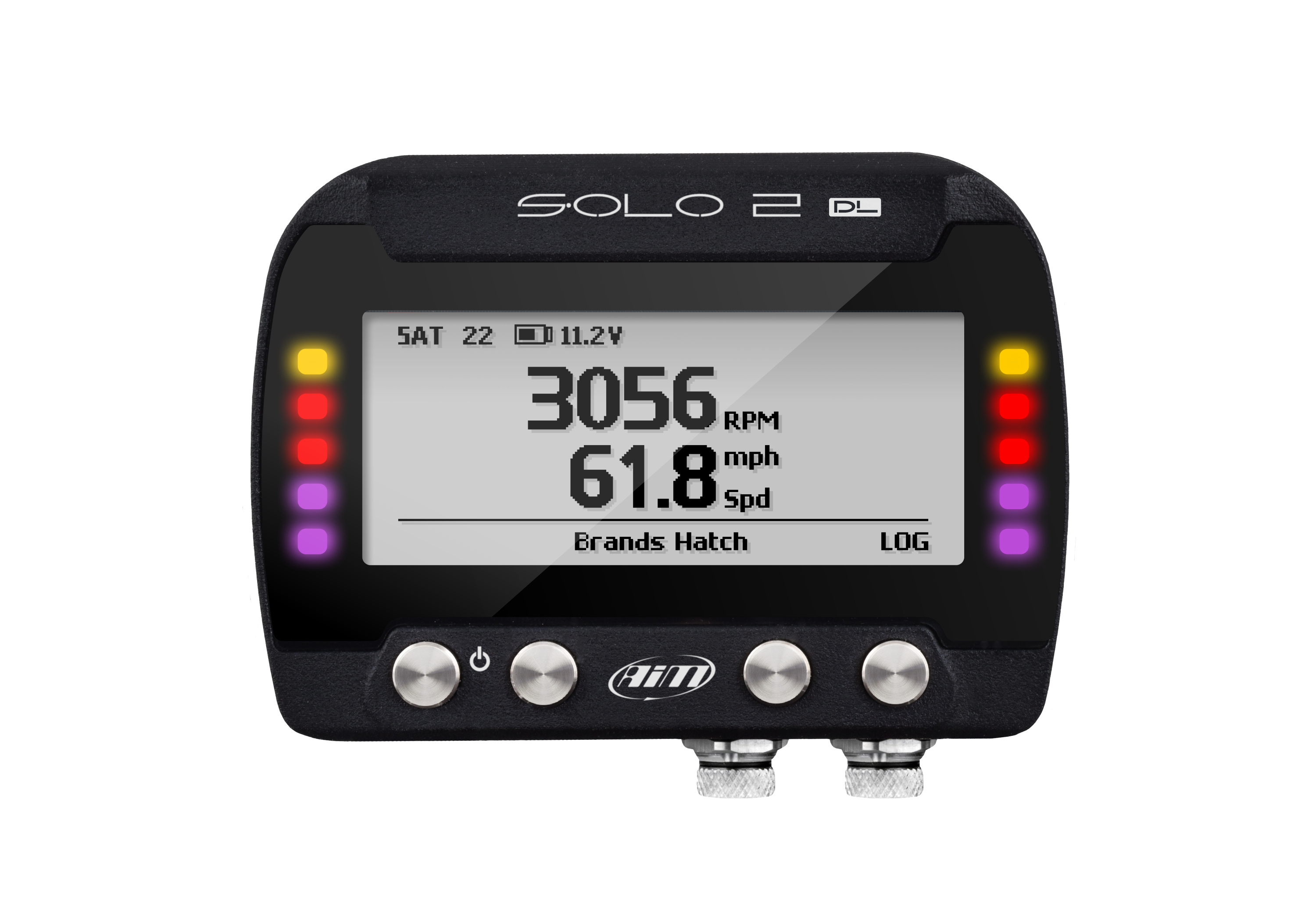
The Solo 2 DL combines GPS-based lap timing, an internal logger, configurable display pages and ECU connectivity. Its ECU interfaces include CAN, RS232 and K-Line; the specific cable and protocol are selected for the installation. AiM also describes an RPM connection for vehicles without a compatible ECU. The unit can associate recorded information with position and lap timing, and uses Wi-Fi to communicate with Race Studio 3. The Solo 2 DL user guide and cable and part-number sheet describe these options.
The standard Solo 2 also records GPS and inertial data, but it is the DL version that adds the ECU connection. An OBD-shaped connector alone does not establish that a particular car or desired parameter is supported; check the exact vehicle, ECU and cable.
EVO6

The EVO6 is a standalone logger with CAN, RS232 or K-Line ECU connection, an internal three-axis accelerometer and gyroscope, and provision for external sensors. AiM lists eight configurable analogue inputs, four speed inputs and a coil-RPM input, plus a second CAN connection. The listed kits include a GPS09c module and harness; cable length and GPS mounting version depend on the selected kit. It has no integrated dash display. See the EVO6 product specification.
The related EVO6L has a different input and connector arrangement, so select by required channels and harness rather than treating the two models as interchangeable. AiM lists the older EVO5 separately as out of production; it may still be encountered on existing cars. The current AiM logger catalogue describes EVO6L and the compact XLog, which includes GPS and a battery.
MXG 1.3 dash logger
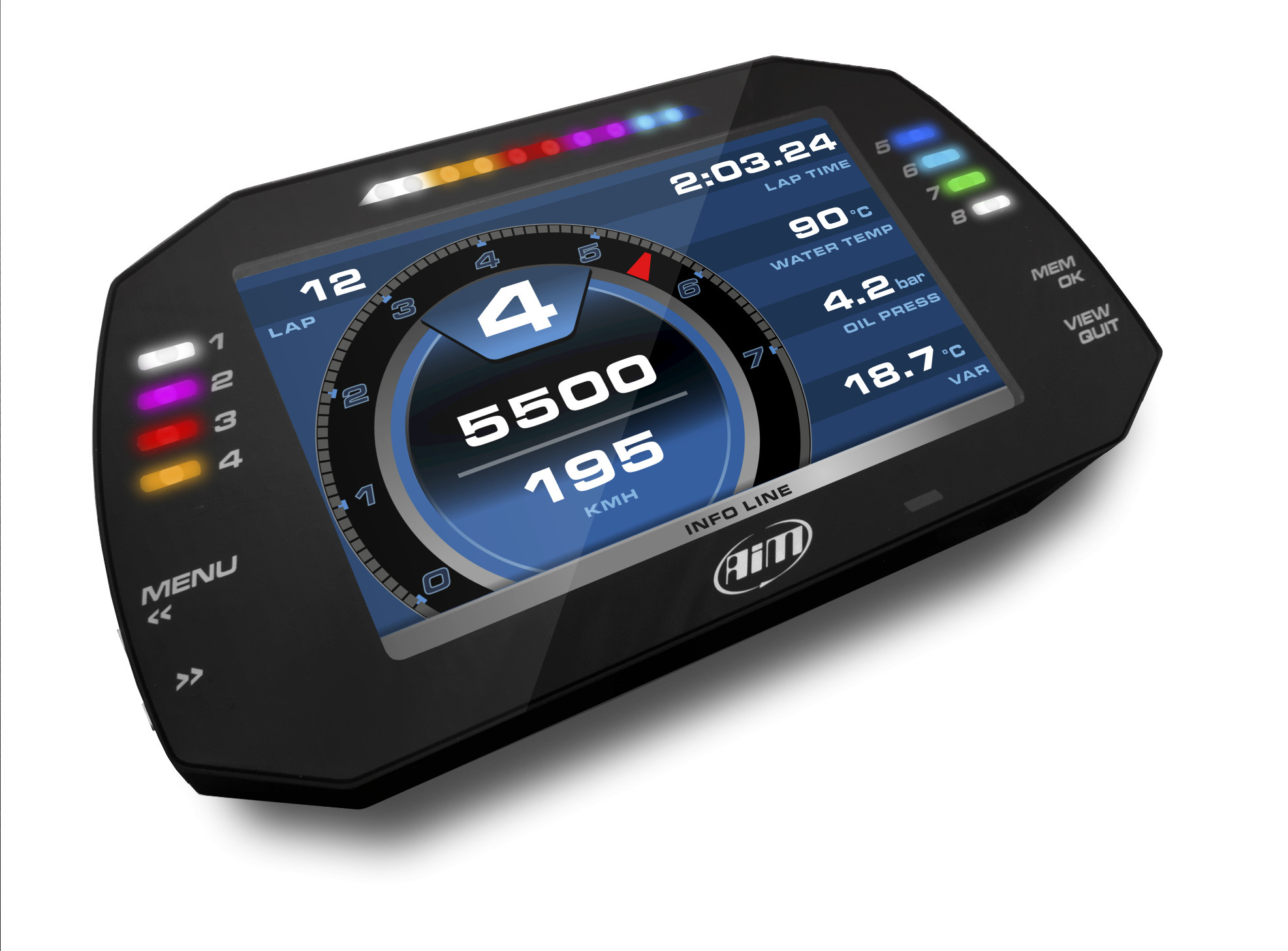
The MXG 1.3 is a 7-inch TFT motorsport display and logger with configurable alarm and shift LEDs. AiM lists three CAN connections, ECU communication through CAN, RS232 or K-Line, eight configurable analogue/digital inputs, speed and RPM inputs, an inertial platform and internal logging memory. A GPS module and other expansions are available; check the exact kit contents. AiM MXG 1.3 specification and documentation.
Model suffix matters: AiM's MX family comparison distinguishes the dash logger from Strada display variants, which do not have the same integrated logging provision. Do not select by screen size alone.
Other AiM logger and expansion modules
- EVO6L: five configurable analogue inputs, two speed inputs, coil RPM and one output; uses different connectors from EVO6. Both support external GPS09c and compatible expansions. The EVO6/EVO6L comparison specifies each model.
- XLog: compact ECU logger with internal GPS, inertial measurement, Wi-Fi and battery. Cable selection determines its connection; it does not have the EVO6's analogue sensor input bank. AiM racing guide.
- ECULog: compact ECU-data recorder; the manufacturer's comparison does not list XLog's GPS and inertial platform on ECULog. Verify the unit and cable when choosing. AiM racing guide.
- GPS09c, ACC3 and LCU: compatible modules add position, analogue/speed inputs or lambda information to a supported logger. A SmartyCam adds synchronised video and overlays; check individual logger compatibility and kit contents. AiM expansion information.

Live telemetry
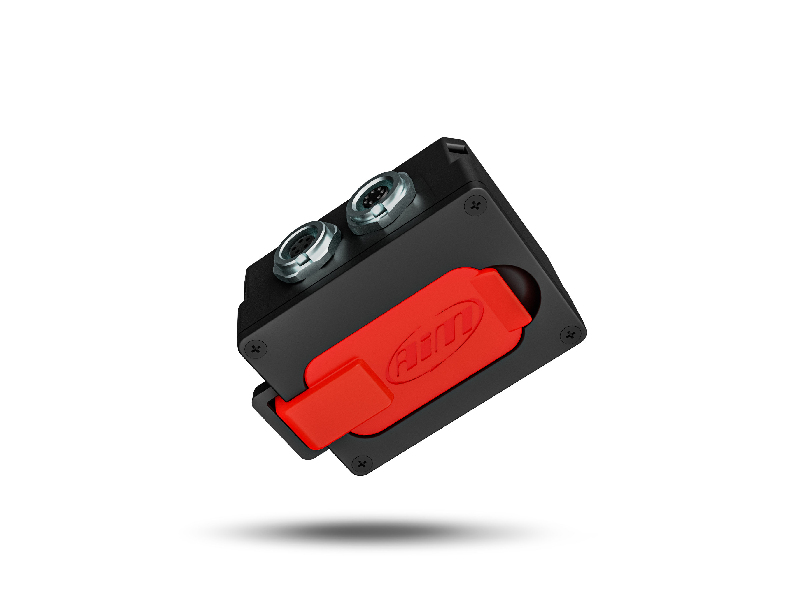
Local Wi-Fi download and a live in-car display are not the same as a remote pit telemetry link. Race Technology documents an optional AiM decoder interface for selected AiM products with its separate RT LIVE system; confirm the listed model, CAN licence, service and cable. The interface does not send messages back to the AiM display. See Race Technology RT LIVE Motorsport and the live telemetry guide.
Cabling and pinouts
Identify the exact device, revision and connector before wiring. These assignments are numbered according to the manufacturer's external-view diagrams of the connectors on the device. Verify the cavity numbering and the relevant device and harness documentation before applying power. “+Vb out”, “+Vb external” and “+Vreference” are different designations: use the manufacturer's electrical and current limits and do not assume they are interchangeable. The tables below transcribe named manufacturer documents; they do not establish a vehicle ECU's pinout.
Solo 2 DL and XLog — Binder expansion and ECU connectors

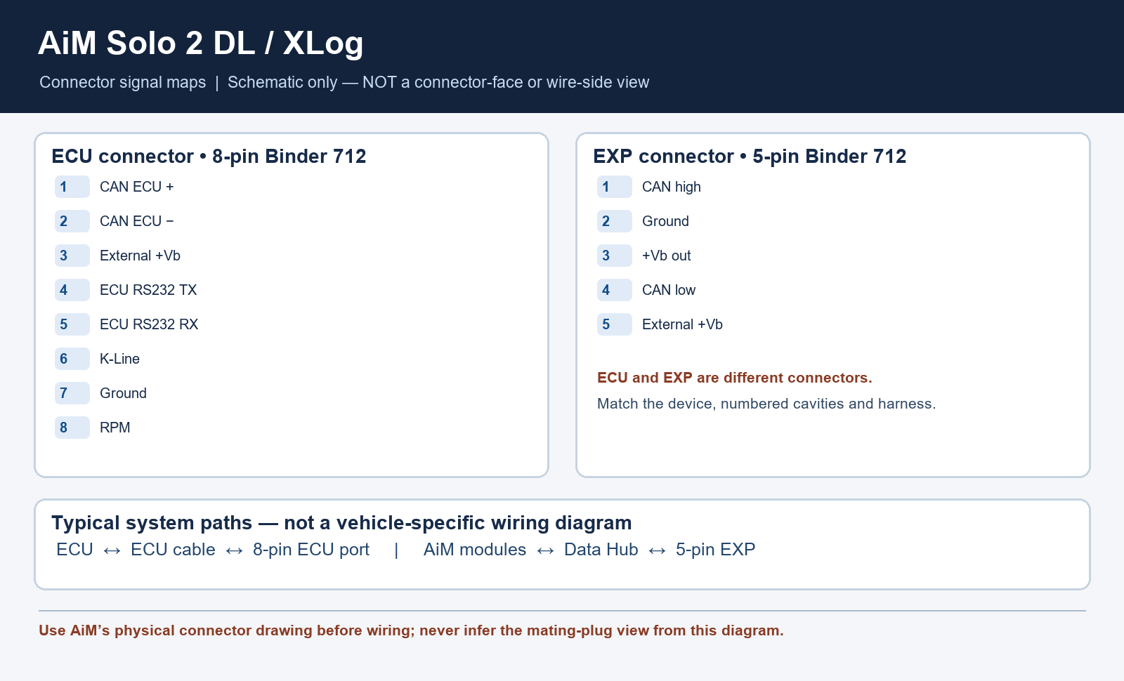
AiM documents a 5-pin Binder 712 female expansion connector and an 8-pin Binder 712 female ECU connector on Solo 2 DL and XLog. Verify the product generation: the original Solo DL is different. Solo 2 DL user guide, pinout; XLog technical sheet, v1.08.
EXP, 5-pin Binder 712 female, device external view:
| Pin | Function |
|---|---|
| 1 | CAN high / CAN+ expansion |
| 2 | Ground |
| 3 | +Vb out |
| 4 | CAN low / CAN− expansion |
| 5 | +Vb external |
ECU, 8-pin Binder 712 female, device external view:
| Pin | Function |
|---|---|
| 1 | CAN ECU+ |
| 2 | CAN ECU− |
| 3 | +Vb external |
| 4 | ECU RS232 TX |
| 5 | ECU RS232 RX |
| 6 | K-Line |
| 7 | Ground |
| 8 | RPM |
ECULog: the ECULog v1.05 sheet shows the same five EXP assignments above but a seven-pin Binder 712 female ECU connector. Pins 1–7 carry, in order, CAN ECU+, CAN ECU−, +Vb external, ECU RS232 TX, ECU RS232 RX, K-Line and ground. There is no pin 8 in that connector. Do not force an eight-pin cable into it.
EVO6L — individual Binder 712 connectors
AiM's EVO6L technical sheet, page 3 identifies female device connectors in external view. This is EVO6L, not the EVO6's multiway harness. The seven-pin ECU connector uses pins 1–7 as listed above for ECULog; AiM labels pin 3 “9–15V Power In” and pin 7 “GND batt”. Its five-pin EXP and GPS connectors use the EXP table above, with AiM labelling pin 3 “+Vbout CAN” and pin 5 “+Vbext CAN”.
| EVO6L connector | Pin assignments |
|---|---|
| POWER, 2-pin | 1: 9–15 V power in; 2: battery ground |
| CH1–CH5, each 4-pin | 1: corresponding analogue input; 2: analogue ground; 3: +Vbout; 4: Vref |
| Speed, 4-pin | 1: speed 1; 2: ground; 3: +Vbout; 4: speed 2 |
| Beacon, 4-pin | 1: magnetic lap; 2: ground; 3: +Vbout; 4: optical lap |
| RPM/Dout, 5-pin | 1: RPM; 2: PGND; 3 and 4: not connected; 5: digital output |
| USB, 3-pin | 1: USB D+; 2: USB D−; 3: ground |
MXG 1.3 and EVO6 — 37-pin main connector
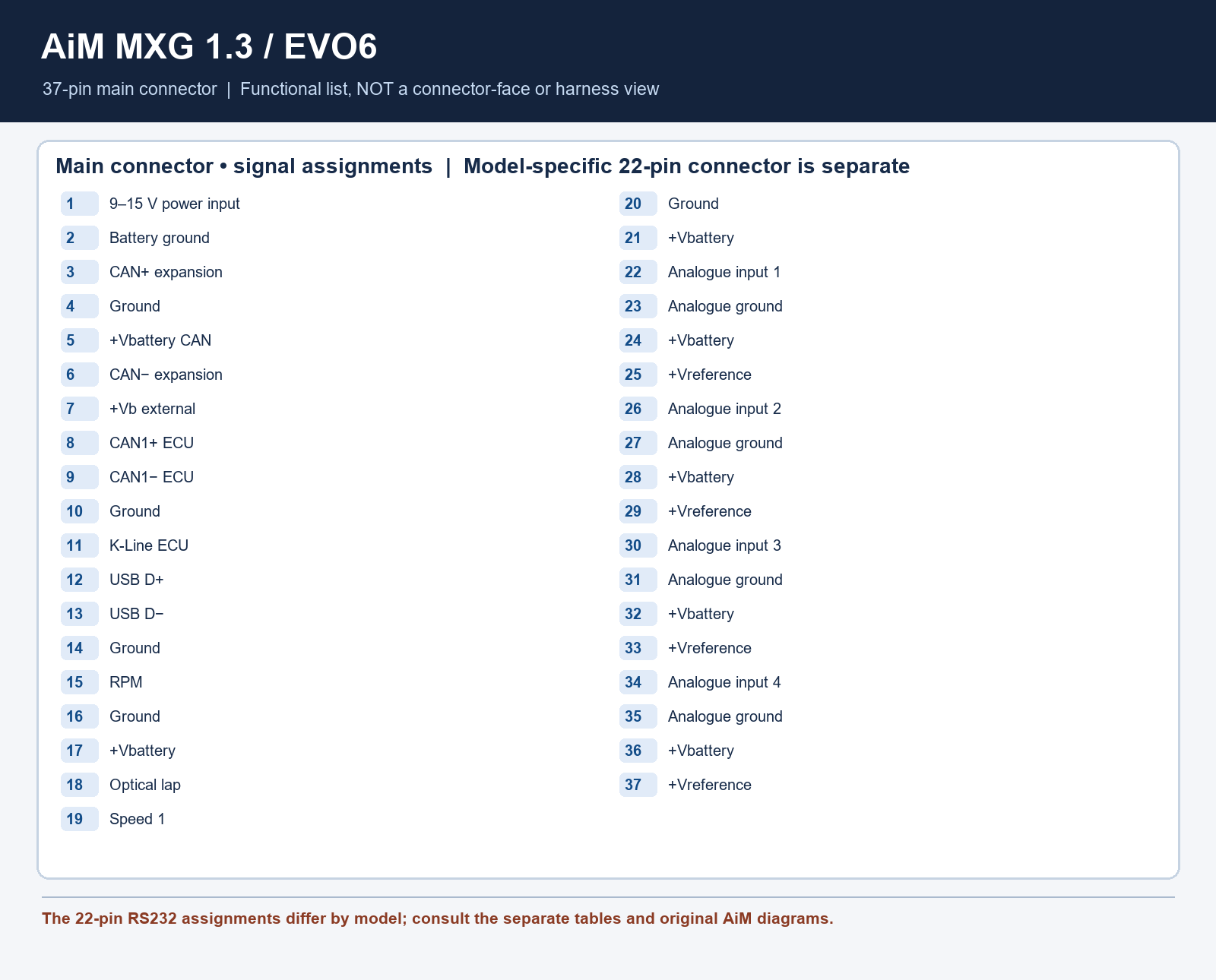
The following assignments match both the MXG 1.3 technical sheet v1.02, page 4 and the EVO6 technical sheet, page 3. Both sheets caption their 37-pin pinout as Deutsch male, external view. AiM's EVO6 product information describes motorsport connectors and its store lists a 37-pin Deutsch harness with an Amphenol adapter: check the actual logger, adapter and harness before specifying mating hardware.
| Pin | Function |
|---|---|
| 1 | 9–15 V power input |
| 2 | Battery ground |
| 3 | CAN+ expansion |
| 4 | Ground |
| 5 | +Vbattery CAN |
| 6 | CAN− expansion |
| 7 | +Vb external |
| 8 | CAN1+ ECU |
| 9 | CAN1− ECU |
| 10 | Ground |
| 11 | K-Line ECU |
| 12 | USB D+ |
| 13 | USB D− |
| 14 | Ground |
| 15 | RPM |
| 16 | Ground |
| 17 | +Vbattery |
| 18 | Optical lap |
| 19 | Speed 1 |
| 20 | Ground |
| 21 | +Vbattery |
| 22 | Analogue input 1 |
| 23 | Analogue ground |
| 24 | +Vbattery |
| 25 | +Vreference |
| 26 | Analogue input 2 |
| 27 | Analogue ground |
| 28 | +Vbattery |
| 29 | +Vreference |
| 30 | Analogue input 3 |
| 31 | Analogue ground |
| 32 | +Vbattery |
| 33 | +Vreference |
| 34 | Analogue input 4 |
| 35 | Analogue ground |
| 36 | +Vbattery |
| 37 | +Vreference |
MXG 1.3 and EVO6 — 22-pin connector
Both sheets show the functions below on their 22-pin connector, described as male Deutsch and viewed externally. Do not swap the RS232 pins between models: the cited MXG sheet labels pin 21 ECU RS232 RX and 22 ECU RS232 TX; the cited EVO6 sheet labels 21 RS232 TX and 22 RS232 RX. Check the relevant drawing, direction conventions and actual harness with AiM before connection.
| Pin | Function |
|---|---|
| 1 | Analogue input 5 |
| 2 | Analogue ground |
| 3 | +Vbattery |
| 4 | +Vreference |
| 5 | Analogue input 6 |
| 6 | Analogue input 7 |
| 7 | Analogue ground |
| 8 | +Vbattery |
| 9 | +Vreference |
| 10 | Analogue input 8 |
| 11 | Speed 2 |
| 12 | Ground |
| 13 | +Vbattery |
| 14 | Speed 3 |
| 15 | Speed 4 |
| 16 | Ground |
| 17 | CAN2+ ECU |
| 18 | CAN2− ECU |
| 19 | Digital output 1 |
| 20 | Digital output 2 |
| 21 | MXG 1.3: ECU RS232 RX; EVO6: RS232 TX |
| 22 | MXG 1.3: ECU RS232 TX; EVO6: RS232 RX |
MXG 1.3 — five-pin camera connector
On the MXG 1.3 the separate five-pin Binder female connector is the camera input, not the EXP connector. The MXG 1.3 sheet labels its external-view pins as follows:
| Pin | Function |
|---|---|
| 1 | Video input 1 |
| 2 | Ground |
| 3 | +Vb output camera |
| 4 | Ground |
| 5 | Video input 2 |
Harnesses and the AiM expansion network

- ECU connection: choose a model-specific CAN/RS232, CAN/K-Line/OBD-II, RPM or vehicle-specific lead. Connector shape alone does not prove ECU compatibility. AiM's Solo 2 DL documentation and cable catalogue list available options.
- MXG 1.3: the standard 37-pin harness provides the main connections; the 22-pin harness adds further inputs and functions. AiM's MXG page links both harness sheets and identifies kit contents.
- EVO6L: select the power, GPS, ECU/CAN or OBD-II, USB and optional RPM/output leads appropriate to the kit; AiM lists part numbers on page 7 of its technical sheet.
- EXP network: Data Hub is an AiM CAN connection multiplier for compatible expansion modules such as GPS, lambda controllers and camera or sensor expansion devices. It is not an analogue sensor interface by itself. AiM describes two- and four-way hubs and supplemental power arrangements in its expansion connection guide. Check power requirements and each device's compatibility before connecting a larger network.
- Sensor cables: use the correct sensor and input type, supply and return. Ground, supply, reference and CAN wires are not identified reliably by colour alone; use the applicable model's drawings, a continuity test with power disconnected and the sensor documentation.
Log-analysis software: Race Studio 3
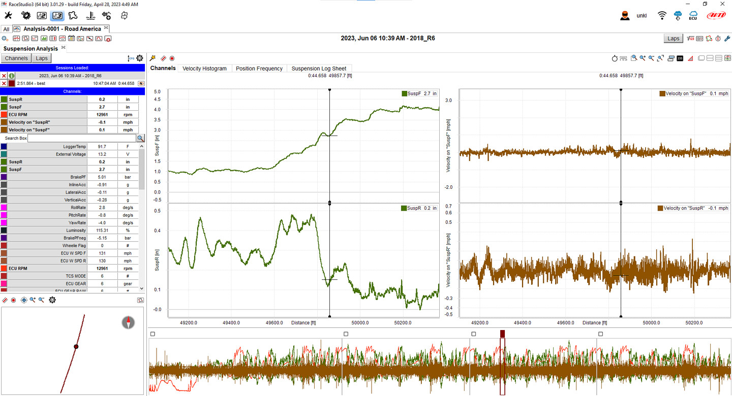
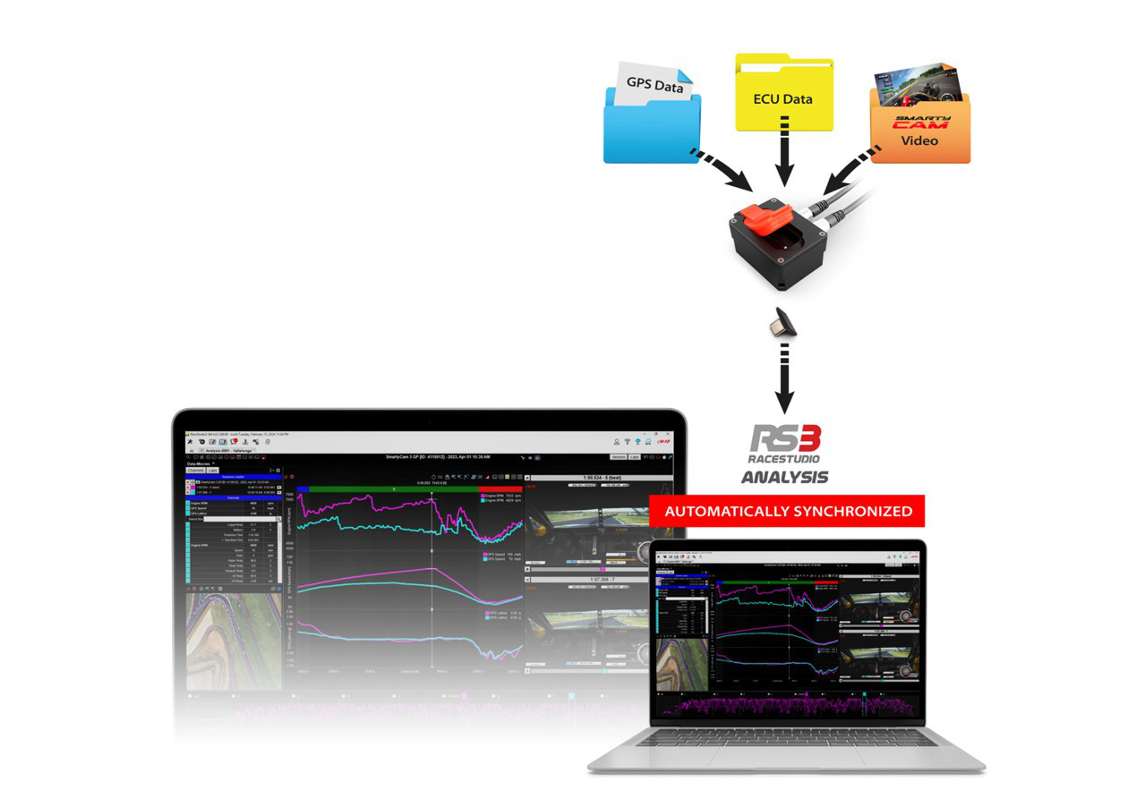
Race Studio 3 is AiM's free-to-download PC suite for configuring compatible devices, downloading sessions and reviewing recorded data in Race Studio 3 Analysis. AiM documents Windows 7, 8/8.1, 10 and 11 support and recommends a recent version of Windows; check the current installer and compatibility information for your computer. Download and device compatibility; operating-system FAQ.
- Analysis: overlay laps or sessions on time/distance graphs, inspect channels and time difference at the same track position, and follow GPS traces on a map when position data is available. The software also provides sector reports, histograms, mathematical channels and a video player for associated recordings.
- Data and sharing: logger download method depends on the unit; for example, Solo 2 DL uses Wi-Fi. AiM documents optional export during download to formats including CSV and MATLAB. Channels available for analysis depend on the actual logger, connected sensors, ECU protocol and configured logging.
- Starting workflow: configure the correct device and channels, download the session, select two laps, plot speed against distance and add time comparison. Inspect the associated track map and video when available, then compare additional channels such as throttle or brake pressure if recorded.
See AiM's Race Studio 3 Analysis manual, data export instructions and analysis training videos. Some cloud storage and services are separate from the basic software; check current terms.
Step-by-step: download and analyse an AiM session
This workflow uses the Windows Race Studio 3 suite and its RaceStudio 3 Analysis component. Menu wording and the available connection depend on the device and software version. GPS, ECU channels and video appear only if the device recorded and transferred them.
- Install the software: download Race Studio 3 from AiM’s software and firmware page, then install it on a supported Windows computer.
- Connect the recording source: finish the session, then power and connect the device using its supported USB, Ethernet or Wi-Fi connection. For Wi-Fi, join the logger’s network first. Alternatively, where the model uses a removable recording card, put the card in a PC reader after recording has stopped.
- Select the recordings: in Race Studio 3, open Devices, select the connected device or detected card and open Data Download. Expand the recording groups and select the desired session and any available video. Check the destination folders and include RaceStudio 3 Analysis in the download preferences if the session should be added to its database.
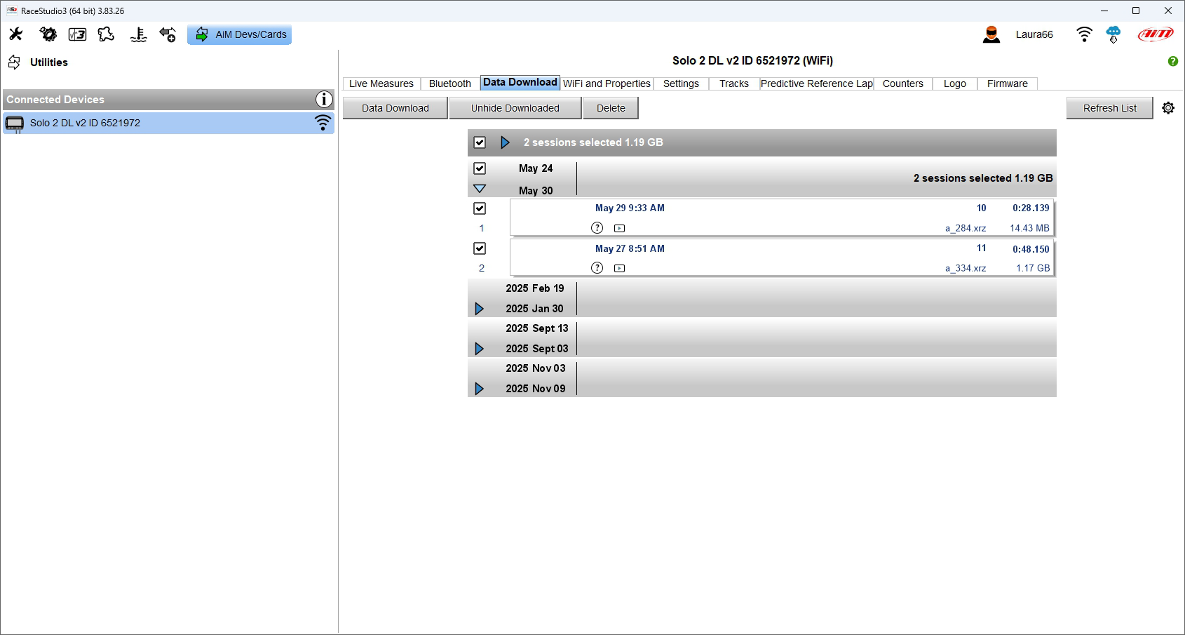
Race Studio 3 version 3.83.26: Data Download for a connected Solo 2 DL v2, showing two selected recordings and the Data Download button. The available connection and list depend on the device and software version. Image: AiM, reproduced with permission; Solo 2 DL user guide, page 65. 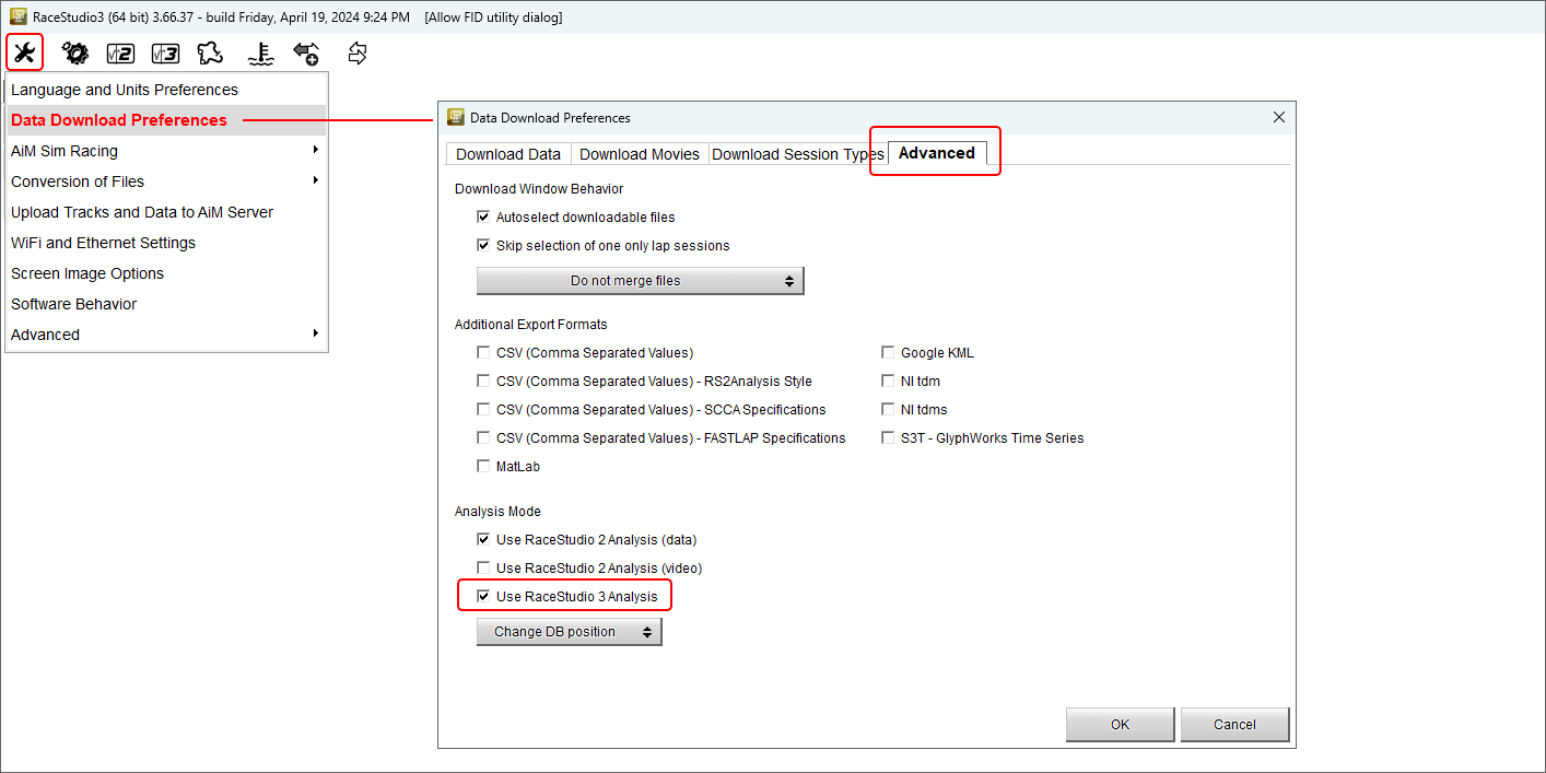
Race Studio 3 Data Download Preferences: enable RaceStudio 3 Analysis so compatible downloaded sessions are added to its database. Screenshot from an earlier software version; controls can vary. Image: AiM, reproduced with permission; manufacturer guide. - Download and check: start Data Download, leave the source connected, and wait for transfer and processing to finish. Check errors and confirm the session is usable before removing any source files. If no file appears, refresh the list or use Unhide Downloaded.
- Open the session: click RS3A on the main toolbar. Find the session in the database, select it and choose Open selected session(s) for analysis. If the files were copied without being imported, use Import new session(s) into database, select the files or folder and wait for the import to finish.

Race Studio 3 Analysis database: choose the session in the centre list and inspect its laps in the preview. Example interface; appearance may vary. Image: AiM, reproduced with permission; manufacturer guide. - Compare a lap: open the Time-Distance Layout, select a recorded channel such as GPS speed in the channels panel, and select the laps to compare. Use distance for comparing the same part of the circuit. Enable Time Compare in graph settings to see time difference against the reference lap; move the cursor and inspect the track map and linked video where available.
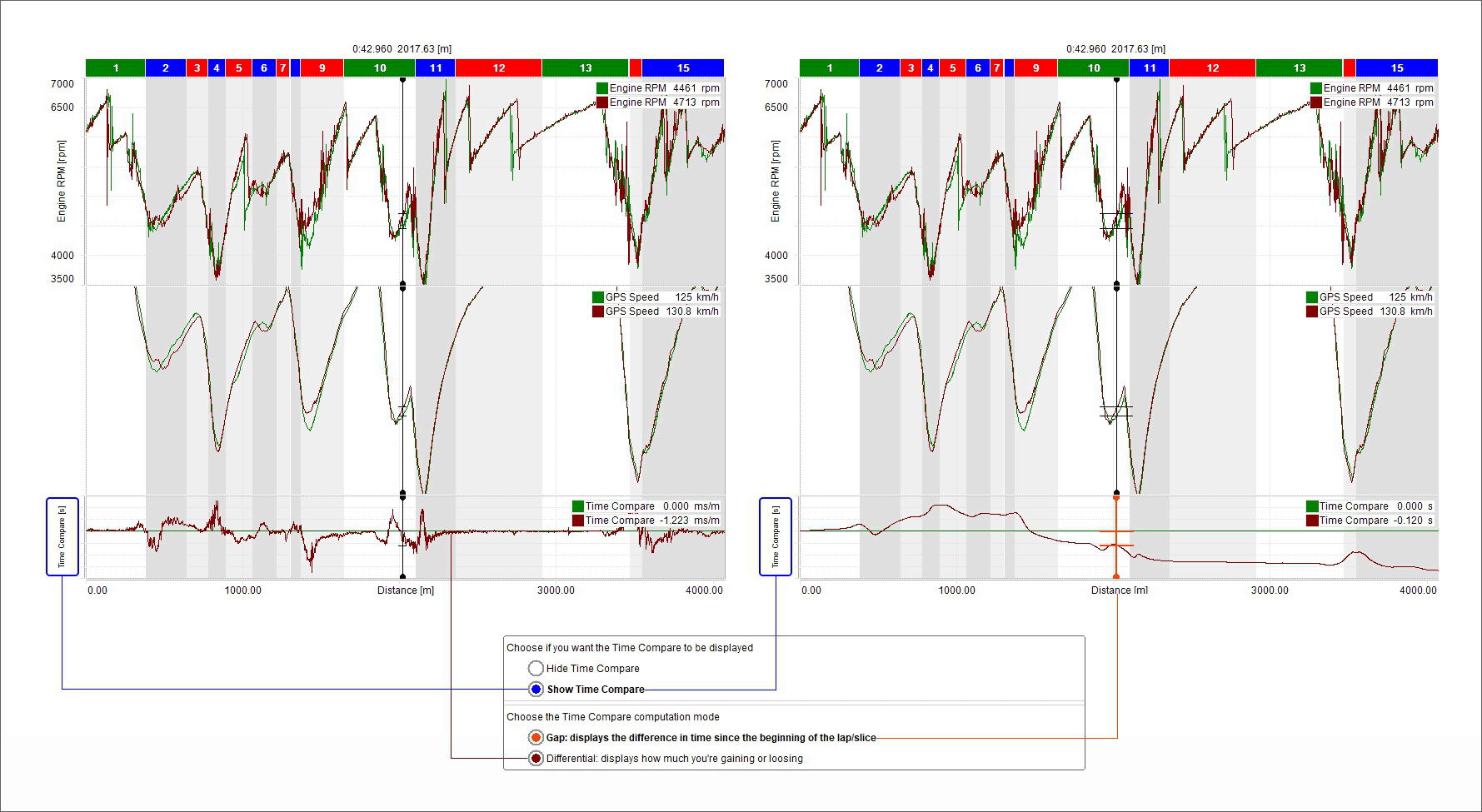
Race Studio 3 Analysis Time Compare examples, with RPM and speed traces plotted against distance and gap or differential modes. Image: AiM, reproduced with permission; manufacturer guide. - Investigate: compare braking, throttle, RPM or other channels actually recorded and check units and sensor calibration. For matched video, open the data-and-movie layout if it is available and ensure the associated video was downloaded. Save a useful analysis profile if you want to reuse the layout.
Sources: AiM’s device and data-download instructions and RaceStudio 3 Analysis guide. Product and connection differences are covered by the individual model guides linked above.
Configuration, analysis and installation
Race Studio 3 is AiM's downloadable configuration and analysis software. Configure the correct ECU protocol and channels, sensor calibrations and logging settings for the unit. Check the trace units and sensor readings against a known reference before interpreting a run; a channel label by itself does not establish measurement accuracy. The MX family page links the software, while the individual product guides cover wiring and setup.
- Confirm whether the information needed is available from the exact ECU and firmware, at a useful update rate. A supported electrical interface does not guarantee every desired channel is exposed.
- Count pressure, temperature, wheel-speed and other sensor inputs as well as any required expansion modules, cables and display or GPS options. Confirm compatibility and electrical limits in the relevant manual.
- Mount the logger securely and follow the model's instructions for orientation and GPS antenna placement. Protect wiring from heat and vibration and follow the manufacturer's electrical guidance.
- For comparisons, record the configuration and conditions, then compare consistent channels and sections of a run. Treat anomalous readings as a prompt to check sensor calibration, wiring and data quality.
Sources: AiM product pages and user documentation linked above. Specifications, kit contents and availability can change; consult the manufacturer for the particular part number. Manufacturer photographs remain credited to AiM.