XLog is a compact ECU logger with internal satellite positioning, inertial sensors and a rechargeable battery. It does not include an integrated dashboard display. For the range overview see AiM in-car dataloggers.

Specifications
| Item | Specification |
|---|---|
| Position and motion | 25 Hz four-constellation GNSS; 100 Hz 3-axis accelerometer and gyro |
| ECU / RPM | CAN, RS232 or K-Line; one RPM input |
| Storage | 4 GB internal and supplied 16 GB removable USB-C drive |
| Connectivity / power | Wi-Fi, USB-C and BLE; rechargeable battery; 9–15 V external |
| Enclosure | 72.3 × 65.3 × 30.3 mm; approximately 150 g; IP65 |
Specifications and kit contents: AiM AiM XLog technical documentation. Check hardware generation and exact kit.
Pinout
AiM identifies female Binder 712 connectors in external device view. The ECU socket has eight pins and is not the seven-pin ECULog socket.
Expansion, 5-pin Binder 712 female
| Pin | Function |
|---|---|
| 1 | CAN high / CAN+ expansion |
| 2 | Ground |
| 3 | +Vb out |
| 4 | CAN low / CAN− expansion |
| 5 | +Vb external |
ECU, 8-pin Binder 712 female
| Pin | Function |
|---|---|
| 1 | CAN ECU+ |
| 2 | CAN ECU− |
| 3 | +Vb external |
| 4 | ECU RS232 TX |
| 5 | ECU RS232 RX |
| 6 | K-Line |
| 7 | Ground |
| 8 | RPM |
Wiring and installation
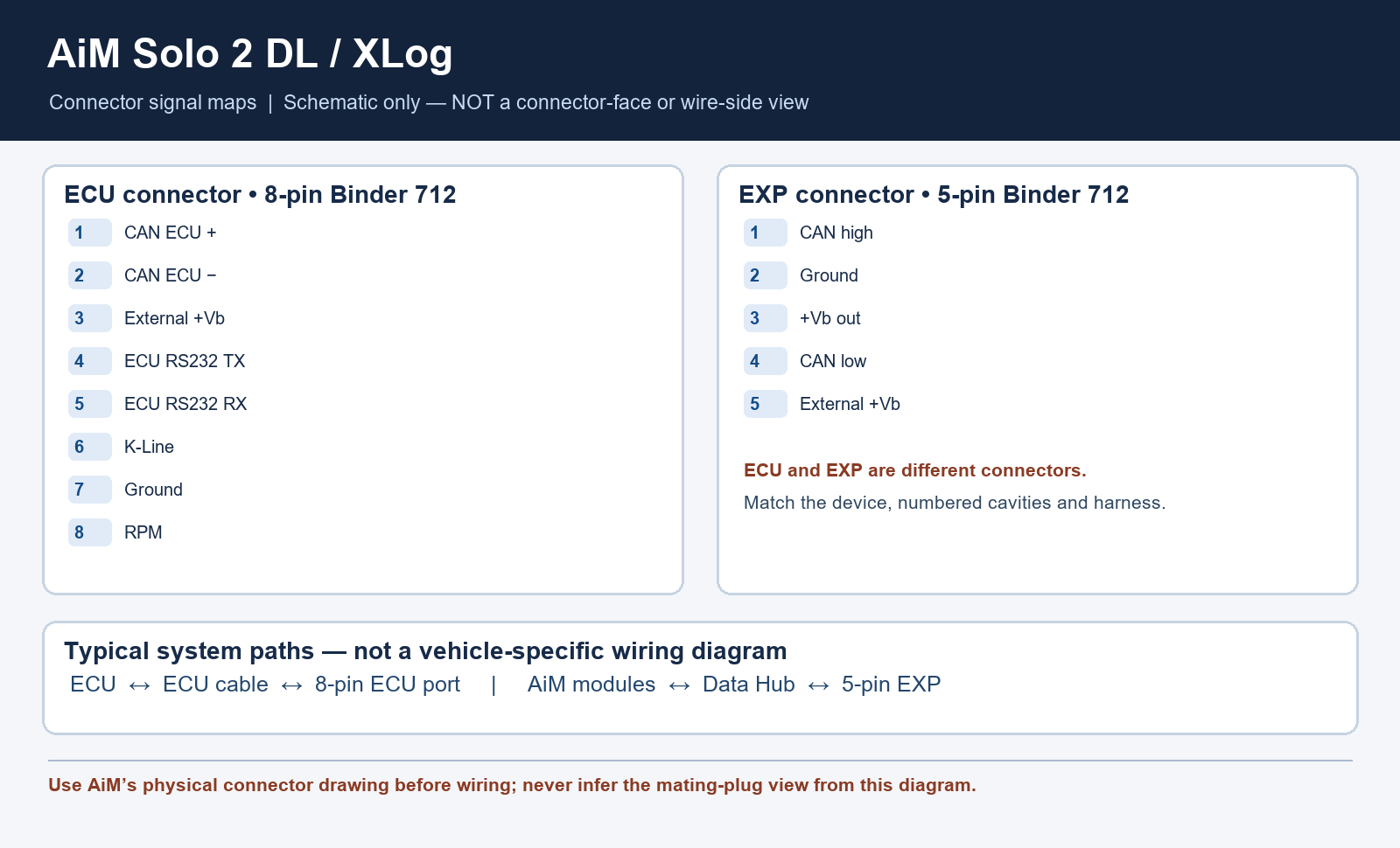
Use the specified CAN/RS232, CAN/K-Line OBD or RPM cable for the installation. An AiM expansion module is required when additional channels are needed; select supported hardware and check external power arrangements.
Choose the correct model-specific lead and configure the ECU protocol in Race Studio 3. A connector shape alone does not establish vehicle compatibility. Confirm every cavity number, signal level, ground, power source and electrical limit in the linked AiM documentation before wiring; diagrams are from the device view or a conceptual schematic as stated. Secure the loom and make connections with power disconnected.
Software and further reading
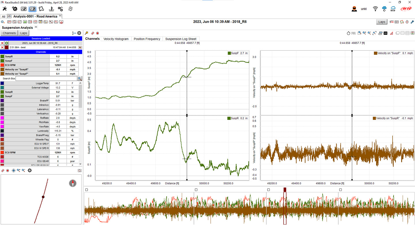
Analysis and download: AiM's XLog guide describes downloading stored sessions into Race Studio 3 and opening them in Race Studio Analysis for graphs and track views. AiM model guidance. Download the Windows software from AiM Race Studio 3 software downloads. For capabilities and compatibility see AiM data-log analysis software.
Use AiM Race Studio 3 to configure supported devices and analyse recorded sessions. Check the specific ECU protocol and cable before connection; not every source exposes every channel. Manufacturer references: model documentation.