MXG 1.3 is a colour motorsport dash with integrated recording. The similarly named Strada display variant must not be assumed to have the same built-in logging. For the range overview see AiM in-car dataloggers.
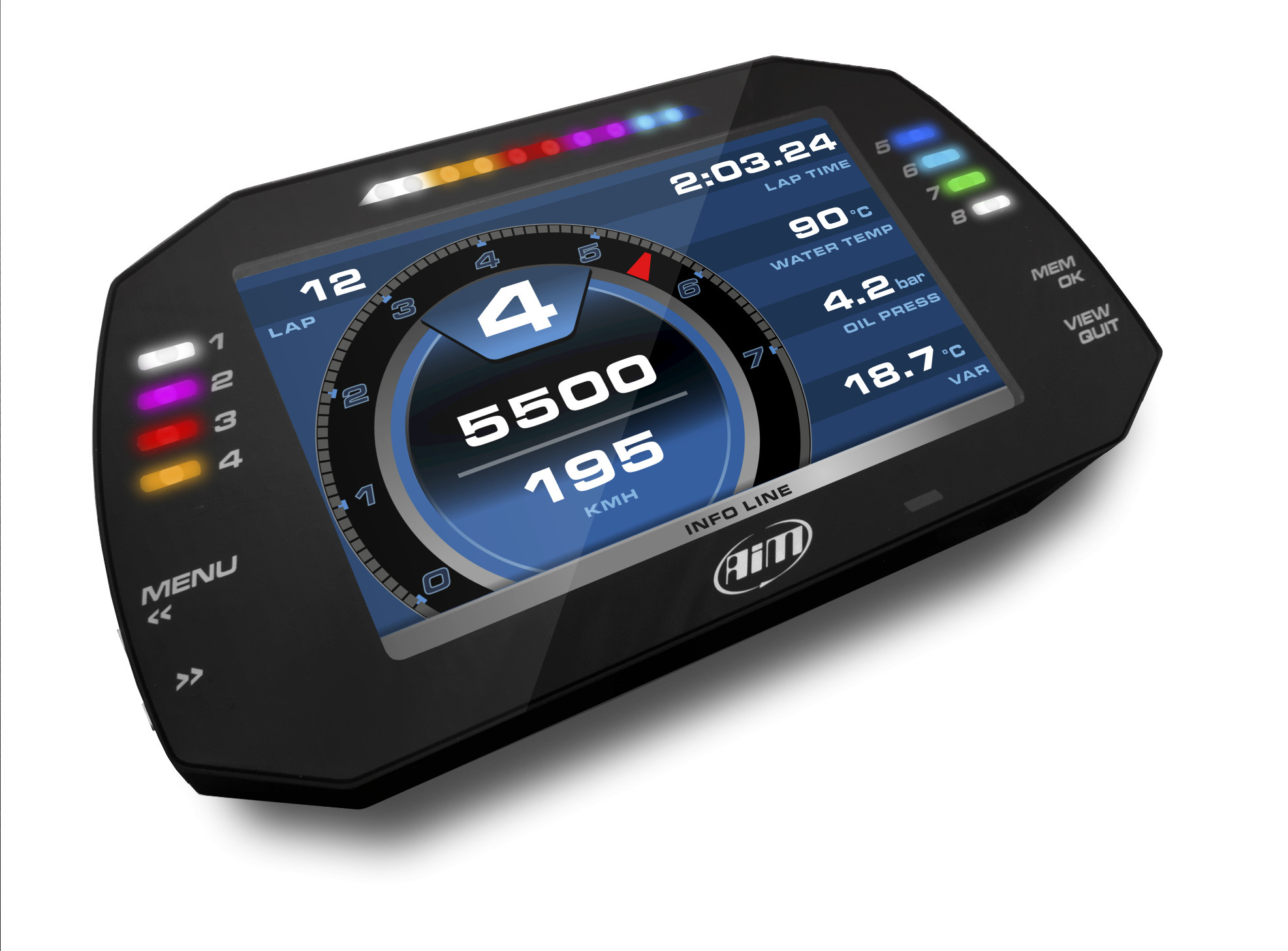
Specifications
| Item | Specification |
|---|---|
| Display | 7-inch TFT, 800 × 480 pixels |
| ECU / networks | CAN, RS232 or K-Line; three CAN connections |
| Inputs | Eight configurable analogue/digital inputs; four speed inputs and RPM |
| Storage / outputs | 4 GB internal; two digital outputs, 1 A maximum each |
| Motion / enclosure | Three-axis accelerometer and gyro; IP67 |
| GPS | GPS09c supplied in listed kits; confirm specific part number |
Specifications and kit contents: AiM AiM MXG 1.3 technical documentation. Check hardware generation and exact kit.
Pinout
The MXG 1.3 sheet shows the 37-pin and 22-pin Deutsch male connectors and separate camera Binder connector in external device view. Its 22-pin RS232 labels differ from EVO6.
Main 37-pin
| Pin | Function |
|---|---|
| 1 | 9–15 V power input |
| 2 | Battery ground |
| 3 | CAN+ expansion |
| 4 | Ground |
| 5 | +Vbattery CAN |
| 6 | CAN− expansion |
| 7 | +Vb external |
| 8 | CAN1+ ECU |
| 9 | CAN1− ECU |
| 10 | Ground |
| 11 | K-Line ECU |
| 12 | USB D+ |
| 13 | USB D− |
| 14 | Ground |
| 15 | RPM |
| 16 | Ground |
| 17 | +Vbattery |
| 18 | Optical lap |
| 19 | Speed 1 |
| 20 | Ground |
| 21 | +Vbattery |
| 22 | Analogue input 1 |
| 23 | Analogue ground |
| 24 | +Vbattery |
| 25 | +Vreference |
| 26 | Analogue input 2 |
| 27 | Analogue ground |
| 28 | +Vbattery |
| 29 | +Vreference |
| 30 | Analogue input 3 |
| 31 | Analogue ground |
| 32 | +Vbattery |
| 33 | +Vreference |
| 34 | Analogue input 4 |
| 35 | Analogue ground |
| 36 | +Vbattery |
| 37 | +Vreference |
Additional 22-pin
| Pin | Function |
|---|---|
| 1 | Analogue input 5 |
| 2 | Analogue ground |
| 3 | +Vbattery |
| 4 | +Vreference |
| 5 | Analogue input 6 |
| 6 | Analogue input 7 |
| 7 | Analogue ground |
| 8 | +Vbattery |
| 9 | +Vreference |
| 10 | Analogue input 8 |
| 11 | Speed 2 |
| 12 | Ground |
| 13 | +Vbattery |
| 14 | Speed 3 |
| 15 | Speed 4 |
| 16 | Ground |
| 17 | CAN2+ ECU |
| 18 | CAN2− ECU |
| 19 | Digital output 1 |
| 20 | Digital output 2 |
| 21 | ECU RS232 RX |
| 22 | ECU RS232 TX |
Camera connector, five-pin Binder
| Pin | Function |
|---|---|
| 1 | Video input 1 |
| 2 | Ground |
| 3 | +Vb output camera |
| 4 | Ground |
| 5 | Video input 2 |
Wiring and installation

AiM lists a main 37-pin harness and optional 22-pin harness. The separate five-pin camera connector is not the CAN expansion port. Check GPS, rear-camera, ECU and sensor lead compatibility and exact kit contents.
Choose the correct model-specific lead and configure the ECU protocol in Race Studio 3. A connector shape alone does not establish vehicle compatibility. Confirm every cavity number, signal level, ground, power source and electrical limit in the linked AiM documentation before wiring; diagrams are from the device view or a conceptual schematic as stated. Secure the loom and make connections with power disconnected.
Software and further reading
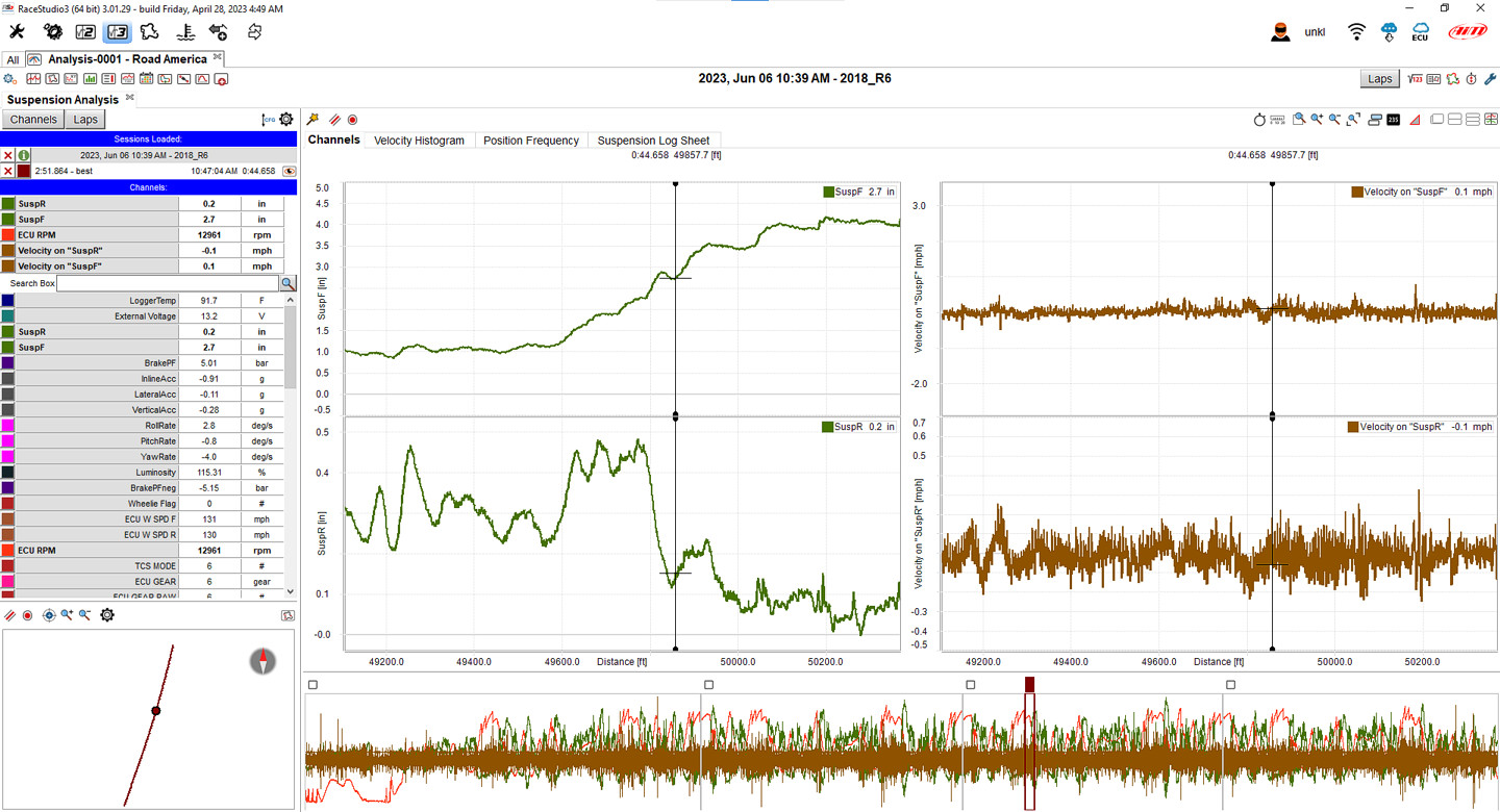
Analysis and download: Race Studio 3 provides setup and PC review of recorded MXG 1.3 data. AiM lists a USB cable in the kit; the recorded channels depend on the configured inputs and connected sources. AiM model guidance. Download the Windows software from AiM Race Studio 3 software downloads. For capabilities and compatibility see AiM data-log analysis software.
Use AiM Race Studio 3 to configure supported devices and analyse recorded sessions. Check the specific ECU protocol and cable before connection; not every source exposes every channel. Manufacturer references: model documentation; product and installation guidance.