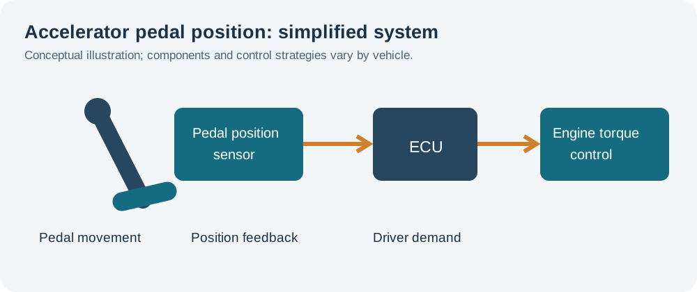
The accelerator pedal position sensor (APP) tells the engine control unit (ECU) how far the driver has pressed the pedal. The ECU uses that information as a request for power. A faulty sensor, poor connection or wiring fault can produce hesitation, reduced response or a warning light, but similar symptoms can come from the throttle body, fuel system, boost control or other engine faults. Test the complete circuit before replacing the pedal assembly.
Symptoms and first checks
| Observation | What to investigate |
|---|---|
| Little or no response to the pedal | Check fault codes, pedal movement, live pedal readings, power and ground, connector and wiring. The ECU may limit output for other faults too. |
| Hesitation or intermittent acceleration | Record when it occurs. Check pedal signal sweeps and harness movement, then investigate fuel, airflow, boost and throttle control as indicated. |
| Warning lamp or reduced-power mode | Save all codes and freeze-frame data. Look for sensor correlation, supply and related actuator faults; a code alone does not prove a failed pedal sensor. |
| Idle speed or response changes unexpectedly | Inspect the pedal and its return movement, signals and related engine faults. Do not assume every idle complaint is caused by the pedal. |
| Fault after water ingress, interior work or a pedal replacement | Inspect the footwell, connector, terminals and harness routing; confirm correct parts, installation and any required configuration. |
HELLA lists loss of accelerator response, limp-home operation and an engine warning light among possible symptoms. A VW Golf 6 Plus example identifies a pedal connector fault as one possible cause for the specified vehicles and codes.
How the pedal signal is used
In an electronic accelerator system the pedal sensor reports pedal position; the ECU interprets it alongside other inputs and operating limits to determine the power request. Petrol engines with electronic throttle control generally use a motorised throttle body with its own position feedback. Many diesels control requested torque principally through fuel injection and may also use an intake throttle for other functions. Systems differ: do not assume that every pedal movement produces the same throttle opening.
Many pedal assemblies provide two independent position signals for plausibility checks. The ECU checks each against its permitted range and the expected relationship between channels. Some use analogue signals and others digital or other designs; the direction, scaling, voltage range, wiring and relationship are specific to the vehicle. A sensor may be integrated into a complete pedal assembly or separately serviceable. Identify the component and circuit before testing.
Pedal position and throttle position are different
The pedal sensor measures the driver’s input; a throttle position sensor measures the throttle valve. The ECU may command a different throttle angle for idle control, traction control, temperature, emissions or protection. Therefore pedal percentage, commanded throttle percentage and actual throttle percentage need not match. Follow the manufacturer’s test conditions and compare the correct parameters.
If pedal signals are implausible at the ECU, investigate their supplies, wiring and sensor. If pedal signals are plausible but commanded and actual throttle positions disagree under a specified test, investigate the throttle actuator, mechanical movement and feedback. Neither observation on its own proves a particular component has failed. See common throttle position sensor faults.

Common causes
- Connector and wiring: loose or corroded terminals, water ingress, chafing or a conductor broken inside its insulation can interrupt one or both channels.
- Power or ground: loss of a specified sensor supply or ground can affect the signal. Some references are shared with other sensors; use the vehicle wiring diagram to trace the circuit.
- Internal sensor fault: a worn track, electronics fault or intermittent signal can occur inside the assembly. Sensor designs vary and not all use a contact track.
- Pedal movement or installation: a damaged pedal, incorrect fitting or a displaced floor mat can restrict movement or prevent full return.
- Related system fault: throttle actuator, fuel, boost or other engine-management faults may limit response even with valid pedal signals.
Fault codes and what they mean
P2120–P2123 commonly relate to throttle/pedal position sensor or switch D circuit, range, low or high input; P2125–P2128 similarly refer to circuit E. P2138 commonly refers to D/E voltage correlation. The full manufacturer-specific definition, circuit assignment and freeze-frame conditions matter: a generic throttle/pedal description does not always identify the exact component. Other codes may concern the throttle actuator, shared reference or a related sensor. Use the manufacturer’s diagnostic procedure and the HELLA code list as a starting point.
Practical diagnostic sequence
- Record the fault. Note whether it occurs on light pedal, full travel, bumps, hot or cold conditions, or after interior repairs. Save all codes, freeze-frame data and relevant live values before clearing them.
- Check pedal travel. With the vehicle safely secured and the system in the manufacturer’s specified state, check the pedal is unobstructed, mounted correctly and returns freely. Examine floor mats and the footwell for water or damage.
- Identify the correct circuit. Obtain the vehicle-specific wiring diagram, sensor type, supply and ground, signal pins, allowable ranges and test conditions. Do not infer pin functions from wire colour or pin count.
- Inspect the connector and harness. Follow the specified isolation procedure. Check for contamination, damaged locks, loose terminals and trapped or chafed wiring. Repair wiring and terminals using approved methods.
- Check live data. With ignition and engine state as specified, slowly move the pedal through its permitted travel and observe each APP channel. Look for dropouts, sticking or implausible disagreement. Scan values may be filtered, scaled or too slow to reveal a brief fault.
- Measure supply and ground. Check each specified reference and ground at the sensor under the conditions prescribed. Investigate related sensors if a shared reference is missing. Use appropriate probes and avoid shorting or spreading terminals.
- Capture both signals. For an analogue system, monitor the specified channels together with a scope while slowly pressing and releasing the pedal, then compare the traces and their relationship with the correct reference. A fast intermittent dropout may be easier to see on a scope. For digital signals, use the specified decoding and test method.
- Localise the problem. If the signal is valid at the pedal but incorrect at the ECU, investigate the intervening wiring and connections. If supply, ground and wiring are correct but the signal fails at the sensor, follow the manufacturer’s component test before replacement. Capture intermittent faults safely under the relevant conditions.
- Repair and verify. Fit and secure the correct assembly or repair the circuit, follow any specified calibration or initialisation, clear codes at the proper stage and repeat the original test. Road-test only when the vehicle is safe to drive.
Secure the vehicle against movement and use the manufacturer’s ignition and transmission precautions. Electronic throttles can move unexpectedly: keep hands clear and do not force the plate or bypass safety circuits. Do not drive a vehicle with unpredictable acceleration or a pedal that fails to return correctly.
Reading a pedal waveform
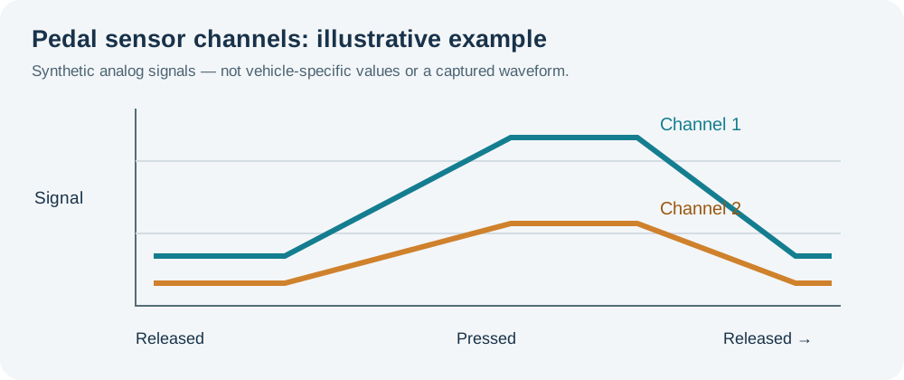
On an analogue design, a smooth pedal movement should produce the changes specified for that sensor. Look for unexpected spikes, gaps, flat spots or a channel that does not track its required relationship. Compare voltages and direction with the correct vehicle reference; channels may have different scaling or change in different directions. A smooth trace does not prove the calibration or relationship is correct. A digital system requires a different interpretation; Pico’s digital pedal test shows why the sensor type matters.
Repair and final checks
Some manufacturers supply the sensor and pedal as one assembly. Confirm the correct part and fitting, preserve wiring clearance and secure the connector. Do not adjust a sealed sensor, alter its signal or assume a universal reset sequence. Carry out a relearn only if the vehicle information requires one. Confirm full travel and return, check pedal readings and fault memory, and repeat the original complaint under safe conditions.