Low boost, hesitation or a pressure-loss fault does not automatically mean that the turbocharger has failed. Diagnose the complete air, boost-control, fuel and engine-management system, and compare the fault with measurements taken under the conditions in which it occurs. The following workshop case shows how a misleading pressure-loss fault led through the intake and boost-control system to an inaccurate air-mass meter.
Oxygen-sensor feedback can help investigate fuelling during a boost complaint. See common oxygen sensor faults.
Temperature-sensor faults can also accompany drivability and boost complaints. See common coolant temperature sensor faults.
Where to look first
| Symptom or observation | Checks to consider |
|---|---|
| Low boost or poor response | Compare requested and actual pressure; inspect intake and charge pipes, intercooler, actuator, control circuit and exhaust restriction. |
| Boost rises then falls, or power returns after a restart | Record the moment of intervention, fault codes, throttle and control signals. A protective response can follow a real pressure fault or an implausible input. |
| Whistle or hiss under load | Inspect charge hoses, connections and intercooler for leaks; also check exhaust leaks and turbo condition. Noise alone does not identify the failed part. |
| Smoke or oil consumption | Check air restriction, breather and crankcase pressure, oil feed and drain, engine condition and turbocharger. Smoke colour alone is not a diagnosis. |
| Boost reading and behaviour disagree | Check sensor supply, wiring, pressure units and gauge location; compare with a suitable independent measurement and other load signals. |
Use the vehicle-specific test plan and limits. Garrett's troubleshooting chart lists related causes for loss of power, noise, smoke and oil consumption.
Understand the readings before testing
Absolute pressure includes atmospheric pressure; a boost gauge usually displays pressure above atmosphere. At an illustrative atmospheric pressure of 1.0 bar, 1.5 bar absolute corresponds to about 0.5 bar gauge. Local atmospheric pressure varies, so use the measured barometric pressure for a precise comparison. Also check whether both instruments measure the same point: a restriction or throttle can create a pressure difference across the system.
With the ignition on and engine stopped, manifold absolute pressure and barometric pressure should be plausible for local conditions and the relevant sensor tolerance. A disagreement is a reason to investigate sensor data, wiring and test equipment, not automatic proof that either sensor has failed.
Reading a boost log
- Actual stays below requested: investigate leaks, restrictions, exhaust energy, actuator movement and control. A single trace cannot distinguish these by itself.
- Actual overshoots: inspect the control mechanism and response using the correct system procedure; sticking geometry, a wastegate fault or a control issue are possibilities.
- Both request and actual fall: look for a change in load, driver demand or ECU limitation, and correlate fault and intervention information. Do not assume a turbo fault.
- Gauge and scan value differ: check absolute versus gauge units, barometric pressure, sensor location, timing and accuracy before condemning a sensor.
Use comparable engine speed, load and temperature for before-and-after logs. A road test must be lawful and suitable for the conditions; use a second person to operate or observe equipment where needed.
Charge-air and oil checks

Inspect the entire charge path, including the intercooler end tanks and hose undersides. Oil mist can make a leak easier to spot, but oil traces alone do not locate the leak. A static pressure test may not reproduce a split that opens with movement or temperature, and it only tests the components within the sealed section.
If oil is found in the intake or exhaust, check the engine's oil level, crankcase ventilation and the turbo oil return as well as the turbo itself. Restricted intake or drainage and excessive crankcase pressure can affect oil leakage; establish the cause before replacing a charger. See Garrett's oil-sealing explanation.
Control systems differ
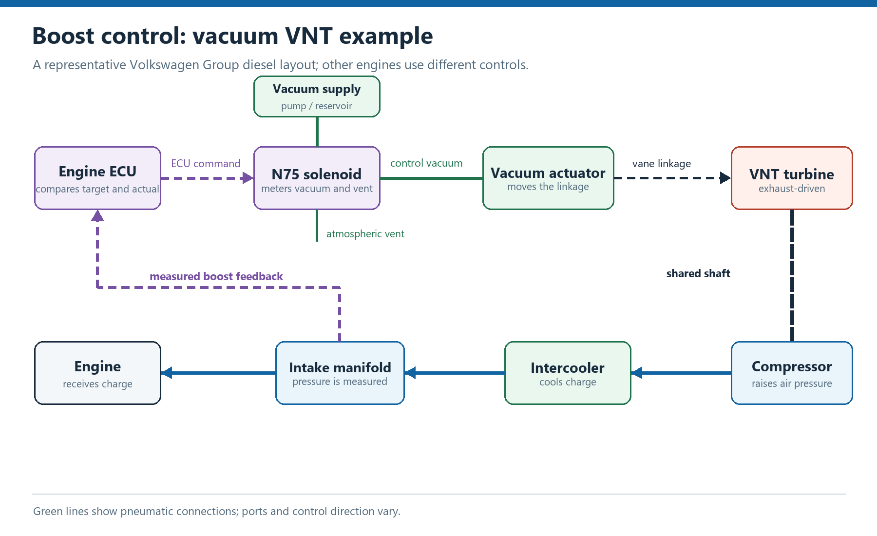
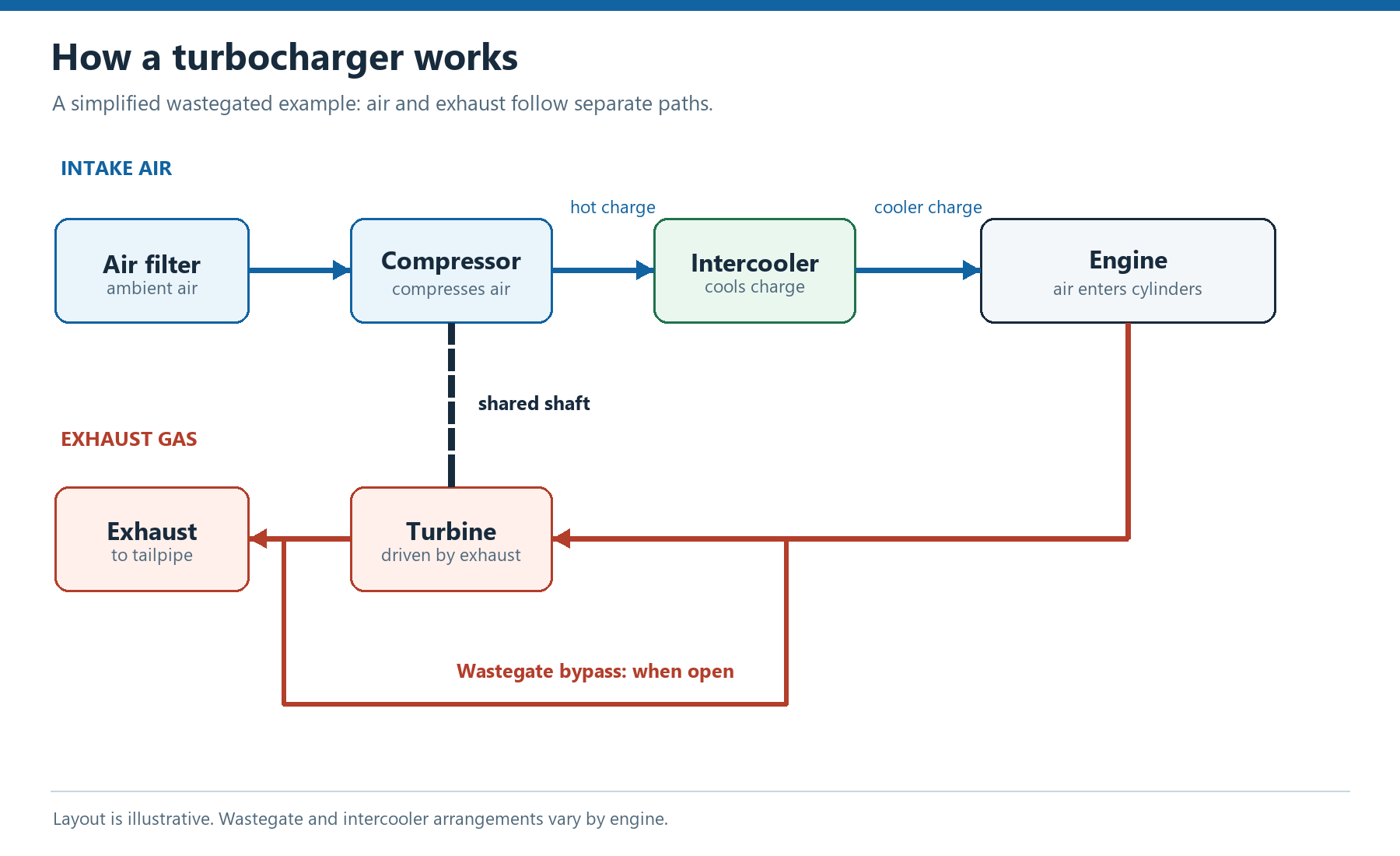
A pressure-operated wastegate, vacuum-operated variable geometry and electronic actuator do not share one test or one normal movement. Identify the hardware and follow its specified pressure, vacuum, travel and electrical checks. Do not change factory stops or actuator calibration as a diagnostic shortcut. See actuators, N75 and boost control.
EGR problems can also resemble a boost fault. See common EGR faults: symptoms, checks and diagnosis for the relevant checks.
An exhaust restriction or DPF pressure-sensor fault can also coincide with reduced power. See common DPF faults for filter and regeneration diagnosis.
Fuel-supply or injector faults can produce similar drivability symptoms. See common injector faults for the relevant checks.
Low fuel delivery can resemble a boost complaint. See common fuel pump faults for pump and pressure diagnosis.
A fuel-pressure reading or supply fault can also accompany loss of power. See common fuel pressure sensor faults.
For MAP and boost-sensor wiring, absolute pressure and plausibility checks, see common MAP sensor faults.
Start with the complaint and the fault record
Record when the loss of power occurs, whether it is sudden or progressive, the engine speed and load, and whether the fault returns after a restart. Ask what work was carried out before the symptoms began. Read and save all fault codes and freeze-frame information before clearing anything. A code identifies a condition seen by the controller; it does not, on its own, prove which part is defective.
For a pressure-drop fault between the turbo and throttle, inspect the charge pipes, intercooler, vacuum and breather connections, diverter system and boost control. A dirty throttle can also be relevant. Ross-Tech lists these as possible causes for 17705/P1297; the exact diagnostic procedure and fault interpretation must match the vehicle.
Workshop diagnostic sequence
- Confirm the complaint and save codes, freeze-frame data, recent work and operating conditions. Identify the engine, control system and any modifications.
- Inspect the air filter, intake tract, charge pipes, intercooler, hose clips, vacuum supply and breather system. Repair evident faults and retest.
- Use the correct leak test and equipment for the system. A smoke test and a regulated pressure test answer related but different questions; isolate or protect components as the manufacturer specifies.
- Check the wastegate or variable-geometry actuator, linkage, control valve and hoses with the manufacturer's method. Do not adjust a calibrated actuator simply to make the reading fit.
- Log requested and actual boost, engine speed, load, throttle position, air mass, relevant control duty and any fault or torque intervention. Compare a suitable independent gauge with scan data, using consistent pressure units and measurement locations.
- If pressure falls, determine whether it is a physical loss, a restriction, a control fault or an intentional response to another implausible input. Check exhaust restriction and engine condition when the evidence supports it.
- Check fuel delivery and mixture information where relevant. Use a scope or validated test equipment to examine the sensor and injector signals when scan data cannot show the timing clearly.
- Verify suspect sensor wiring and plausibility against vehicle-specific data. A substitution or disconnection can help isolate a fault, but the resulting default operation is not conclusive on its own.
- After repair, restore all connections, clear codes as appropriate and repeat the original test. Confirm actual and requested values, fault memory and drivability.
For a dedicated guide to air-mass readings, wiring and intake leaks, see common MAF sensor faults.
Case study: Golf GTI 1.8T with restricted boost
A 2001 Volkswagen Golf GTI 1.8T, using Bosch ME7.1 management and a water-cooled K03 turbocharger, lost power suddenly at a steady road speed of roughly 50 mph after a service. The loss remained, with occasional hesitation and misfire and a noticeably weak turbo response. The controller recorded a pressure-loss fault between the turbocharger and throttle.
First checks and repairs
The intake and intercooler circuit was smoke-tested. Several breather and vacuum-control hoses leaked; the spark plugs were sooty and the ignition coils were in poor condition. These defects warranted attention, but none was assumed to be the sole cause of the boost complaint. The throttle intake hose was removed, the throttle plate cleaned, adaptations reset and fault codes cleared. A further drive showed the same lack of power and the same pressure-loss fault.
Cleaning or adaptation resets are not universal remedies. Follow the vehicle-specific throttle cleaning and alignment procedure, and record learned values where appropriate before resetting them. Retest the original complaint after each repair.
Wastegate and control checks
The technicians applied regulated pressure to the wastegate actuator while watching its movement. In this particular vehicle it began to open at approximately 0.8 bar and was fully open between about 1.2 and 1.5 bar. They also checked the N75 boost-control solenoid for operation and leakage and checked that the vacuum-operated recirculation valve moved freely. The spring in the recirculation valve affects its behaviour, but changing a spring is not a diagnostic repair for this fault.
These pressures are observations from one car, not universal actuator specifications. Actuator type, preload, pressure or vacuum range and the relationship between solenoid duty and boost vary by system. Check the correct manufacturer's procedure. The N249 control solenoid and the vacuum-operated diverter valve it controls are separate components on systems arranged this way; inspect the hoses and each component in the applicable circuit.
Mechanical boost measurement
A mechanical pressure gauge was connected to the intercooler circuit and boost was observed under load. With the controls connected normally, pressure rose initially but did not exceed about 0.5 bar; the original fault returned. In a further historical test with normal wastegate control bypassed, the gauge briefly indicated about 1 bar before falling again to approximately 0.5 bar under sustained load. The technicians had expected a higher reading in that test.
Bypassing wastegate control can produce uncontrolled boost and turbo overspeed. The historical test is included to explain the investigation, not as a recommended road-test procedure. Use the manufacturer's controlled tests, observe specified limits and stop if boost exceeds them. A gauge reading must also be identified as gauge pressure or absolute pressure before it is compared with scan data.
Checking restrictions and leaks again
The team considered an internal leak, exhaust restriction and a turbocharger fault. They temporarily separated the exhaust downstream of the turbo and saw no improvement, then inspected the wastegate and associated movement. Although the earlier smoke test had found and corrected leaks, they also questioned whether another leak opened only under pressure. With the relevant control valves isolated, a static pressure test held 2 bar without an apparent leak.
That result applied to the portions of the system actually included and isolated in the test; it did not prove that every valve or hose would behave correctly under all running conditions. For current work, use a regulated supply and the vehicle manufacturer's pressure limit, secure the connections and protect components that cannot tolerate the test pressure. Inspect the intake, intercooler and exhaust systematically; restrictions and leaks can produce symptoms resembling turbo failure. Garrett's diagnostic guide gives a broader list of checks.
Comparing scan data with the gauge
The team logged boost-control data with VAG-COM and compared the indicated pressure with the mechanical gauge. The system entered a default operating mode very quickly, limiting the opportunity to assess normal control. In that state, the reported N75 duty was approximately 5% and boost remained near 0.5 bar. The meaning of a duty-cycle number depends on the control strategy and display convention; do not transfer that value to another vehicle as a pass or fail threshold.
During a further test the turbo briefly reached approximately 1 bar, but under sustained load pressure again fell to 0.5 bar. The motorised throttle reading simultaneously fell from approximately 100% to 20%. This was an important observation: reduced airflow could be a commanded response to a perceived fault rather than evidence that the turbocharger itself was unable to make pressure. The throttle assembly was checked and appeared normal; the remaining question was why the engine management was intervening.
Air mass and fuelling
Further logging occasionally showed approximately 175 g/s from the air-mass meter at around 1 bar of boost, compared with approximately 150 g/s expected for this case. The high figure initially seemed to argue against a major restriction, but a displayed air-mass value is still a sensor report and must be checked for plausibility. Air mass varies with engine, calibration, speed and conditions; neither figure is a universal specification.
Fuel pressure and delivery were checked with a mechanical gauge and were reported normal. An oscilloscope was then used to compare the oxygen-sensor indication, air-mass signal and injector pulse duration in real time. The technicians found a way to observe the fault before default mode intervened. Before intervention, the reported mixture indication was rich while injector pulse duration continued to increase; in default mode the oxygen-sensor signal behaved more normally. That pointed the investigation towards an incorrect input or a fuelling command overriding the expected response, rather than proving a defective oxygen sensor.
The historical investigation described a broadband oxygen-sensor voltage of about 2.5–3 V around lambda 1, with a lower indicated voltage interpreted as rich on that test setup. Do not use those voltages as a generic wideband sensor test. Wideband sensors and their controller circuits differ; use the correct wiring, measuring points and manufacturer data, and do not assume a raw pump-current circuit can be interpreted like a conventional narrowband signal. Bosch notes that mixture and lambda-related faults can originate in air leaks, fuel delivery or other sensor inputs: Bosch sensor fault diagnosis.
Finding and confirming the cause
The software variant was checked and the latest software reinstalled, but attention returned to the unusually high air-mass reading. Disconnecting the meter for a diagnostic comparison restored normal boost performance. The fitted meter was an unbranded replacement rather than an OE-specification unit. After fitting an OE-quality meter, the peak reading was approximately 150 g/s and boost performance returned.
The case conclusion was that an inflated air-mass signal made the controller's air-mass and pressure information implausible, contributing to the apparent pressure-loss diagnosis and protective intervention. The unplugged test was a clue: substituting a default value changes the control strategy and does not by itself prove the meter is faulty. Confirm wiring, supply, air leaks, part number and sensor plausibility, then verify the repair under the original operating conditions.
For further system detail see turbocharger actuators and boost control, diverter valves and airflow sensors.
For a closer look at split hoses, intercoolers and leak testing, see common boost leaks.