What controls boost?
Boost control has several separate parts. The ECU decides a target using the engine's operating conditions, reads pressure and other sensors, and commands a control device. An actuator moves a wastegate or variable-geometry mechanism; a pressure-control solenoid may sit between the ECU and a pneumatic actuator. The feedback, actuator and turbine must be matched to the engine and its calibration.
Wastegate and variable-geometry actuators
An internal wastegate uses a flap in the turbine housing to bypass exhaust around the wheel. An external wastegate performs the same function through a separate valve. On a common pressure-operated internal wastegate, boost pressure acts against an actuator spring and moves a rod to open the flap; the solenoid can vary the pressure reaching the actuator. The spring establishes part of the mechanical response, but the boost actually achieved depends on plumbing, turbine flow, exhaust pressure and ECU control. Do not assume spring rating equals a safe boost target.
A variable-nozzle or variable-geometry turbocharger (VNT/VTG) changes turbine inlet geometry instead of relying on a fixed nozzle. An actuator turns a lever and adjusts the vane ring. Vacuum-operated and electronic versions exist. On a typical diesel vane system, closing the vanes increases turbine drive at low flow and opening them lets more exhaust pass at higher flow. Exact travel, stops and control direction depend on the turbo. Some electric actuators contain a motor, electronics and position feedback, and may communicate using PWM or a vehicle network.
N75: the control solenoid
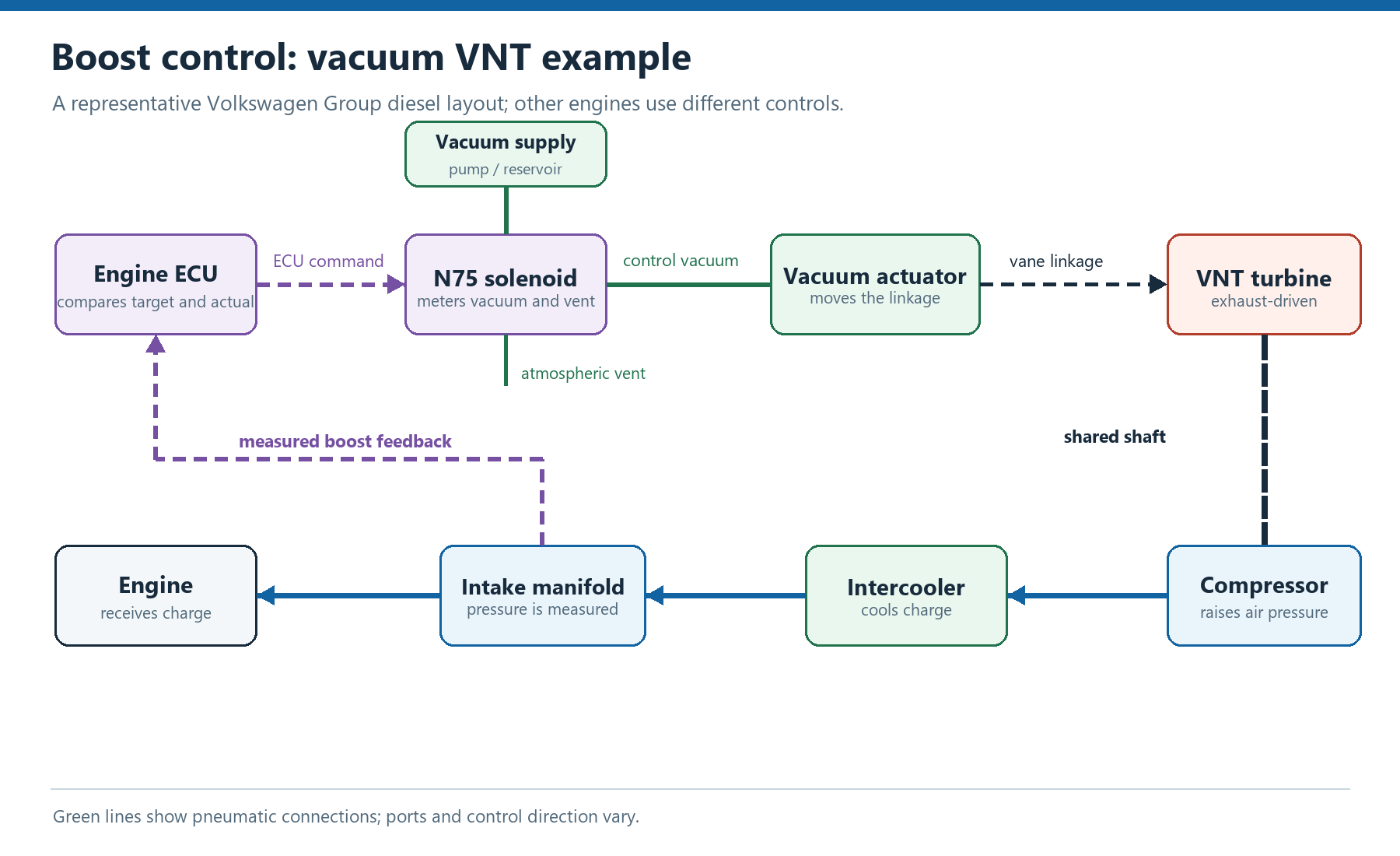
N75 is a Volkswagen Group component designation for a charge-pressure control solenoid, not a universal name for the turbo or its actuator. The ECU pulses it to regulate a pneumatic control signal. The plumbing and function vary by engine. Audi's self-study programme 207 shows an N75 controlling the pressure-operated wastegate on its 1.8-litre petrol turbo example. Volkswagen's programme 190 shows N75 regulating vacuum for the adjustable vanes of its diesel example. Other engines use different components or electronic actuation.
Consequently, do not transfer a hose diagram, port assignment, spring setting or duty-cycle interpretation from one engine to another. Use the correct engine-code wiring and vacuum/pressure diagram. The ECU's displayed duty cycle is a command, not direct proof that the valve, hoses or turbo mechanism responded. A compatible replacement must suit that control system; a different N75 part is not automatically a power upgrade.
Symptoms and diagnosis
Underboost, overboost, a warning light or reduced-power mode can result from leaks, a faulty sensor, a solenoid, wiring, the actuator, a sticking linkage or vanes, exhaust restrictions and other causes. Record the fault codes and freeze-frame context, then compare requested and actual charge pressure and the control command in the conditions where the fault occurs. A fault code identifies a monitored condition; it does not by itself prove which part has failed.
- Inspect charge pipes and intercooler for leaks, and the relevant pressure or vacuum hoses for splits, loose connections, restrictions and incorrect routing. Check the vacuum supply where the design uses one.
- Use the manufacturer's diagnostic output test and wiring information to check the solenoid and its electrical supply/control. A click alone does not prove the valve meters pressure correctly.
- With an appropriate hand pressure or vacuum pump and the correct specification, check pneumatic actuator movement and whether the diaphragm holds its prescribed test pressure. Do not apply vacuum to a pressure-only actuator, exceed its test limits or force the linkage.
- For electronic units, check the connector, power supply, diagnostic feedback and commanded movement using the specified procedure. Stiff vanes or linkage can overload an otherwise functioning actuator.
Boost creep and wastegate flow
Boost creep is a progressive rise in boost as engine speed and exhaust flow increase when the system cannot divert enough exhaust around the turbine. It is one possible cause of overboost; a control fault or incorrect pressure signal can also produce excessive boost. Turbosmart’s actuator troubleshooting identifies a restricted wastegate flow path, inadequate wastegate size and a seized joint as possible causes on its described setup.
On an external-gate installation, the path from the manifold to the valve matters as well as valve size. Garrett’s external wastegate installation guide illustrates how the branch angle and transition affect bypass flow. Its diagrams are guidance for that hardware, not a universal manifold template.
Compare boost target, measured pressure and control command during the event, then inspect the correct pressure source, hose routing, actuator travel and bypass path using the manufacturer’s procedures. A command to open the gate does not prove the valve moved far enough or that the bypass can pass the required flow. Stop the test if pressure exceeds the safe limits for the combination; increasing preload or repeatedly changing control maps does not repair a restricted or sticking wastegate.
Adjustment and replacement
Rod length, preload and vane stop positions affect turbine flow and control. Marking a rod or copying turns is not a calibration. HELLA notes that some turbo and electronic actuator combinations require matching on a flow bench and, depending on the application, a basic setting or learning procedure in the vehicle. Follow the turbo and vehicle manufacturer's procedure; do not adjust factory stops to mask a fault. For a repaired turbo, rotor balancing and vane/actuator flow calibration are separate jobs.
Sources
- Self-Study Programme 207: The Audi TT Coupé. Audi/VW, independent mirror. Example 1.8T N75 and wastegate control. Accessed 2026-11-14.
- Self-Study Programme 190: Adjustable Turbocharger. Volkswagen, independent mirror. Diesel VNT vacuum and N75 control. Accessed 2026-11-14.
- Electronic boost pressure control and actuator testing. HELLA. Electric actuator feedback, diagnosis and matching. Accessed 2026-11-14.
- Turbo Tech 101. Garrett Motion. Wastegates and pressure-operated actuator context. Accessed 2026-11-14.
For a complete diagnostic sequence and a worked example of boost-control intervention, see turbo diagnostics.