Bosch Motorsport supplies configurable motorsport data loggers, combined displays and loggers, sensor interfaces, telemetry gateways and software. A system can combine ECU values with separately measured chassis and engine channels; the available channels depend on the sensors, wiring, communications and activated options. Hardware supporting a telemetry connection still needs the appropriate gateway or radio, receiving service and configuration to report data remotely.
Individual equipment models
- Bosch Motorsport DDU 10
- Bosch Motorsport DDU 11
- Bosch Motorsport C 60
- Bosch Motorsport C 70
- Bosch Motorsport C 80
- Bosch Motorsport CG 3.2
- Bosch Motorsport FM 40
- Bosch Motorsport BT 60
Dash displays with logging

| Model | Recording and identification | Options and connections |
|---|---|---|
| DDU 10 | 7-inch colour display; the documented basic internal logger has 4 GB, 100 channels and a 50 ms (20 Hz) recording interval. | FULL_LOG_1 enables up to 1,500 channels at a 1 ms interval; FULL_LOG_2 adds a second 4 GB partition. USB data copy is optional. Ethernet, CAN and RS232 support additional devices. Read the exact product and firmware documentation. |
| DDU 11 | 6.5-inch colour display; Bosch describes the same basic 4 GB, 100-channel, 20 Hz logger and up to 48 configurable display pages in four sets. | Full logging, a second partition, USB logging and external GPS are options. Bosch lists Ethernet, CAN and RS232 connectivity. GPS and other accessories should be confirmed in the chosen package. |
Maximum channel counts or sampling settings do not guarantee that every external source transmits at that rate, or that all configurations can sustain every maximum simultaneously. Older DDU 7, 8 and 9 appear in the WinDarab supported-device list; support in analysis software alone does not establish an older unit's logging entitlement or current availability.
Standalone loggers and sensor interfaces
- C 70: a standalone programmable logger with 4 GB internal storage, 1,500 channels and 1 ms sampling interval enabled according to its specification. Four analogue and four speed inputs are standard; 12 extra analogue inputs, a second 4 GB partition, USB data copy and CCP/XCP master functions are options. Ethernet and CAN connect additional devices; GPS and telemetry need appropriate equipment. Bosch C 70 specification.
- C 80: available in distinct logger and sensor-interface base versions. The logger version includes a 4 GB first partition; the sensor-interface version has a different initial entitlement. Options increase storage, add channels, enable USB data copy or CCP/XCP master functionality. Bosch describes up to 26 analogue and four digital inputs subject to configuration and upgrades, along with CAN, Ethernet and telemetry support. Confirm the version and enabled keys. Bosch C 80 specification.
- C 60: an earlier compact logger described in Bosch's archived C 60 datasheet. It records ECU and chassis information and has a 2 GB internal logger. Additional analogue channels, USB recording and other functions depend on the upgrade. It may be found on existing cars; verify the particular unit and its supported options.
Telemetry and connected data

The CG 3.2 telemetry gateway combines dual 5G modems with 4G fallback, GNSS, Wi-Fi, wired connections and 16 GB onboard storage. Bosch describes RaceConnect Cloud live telemetry, data distribution and remote configuration, with data plans listed separately. Check network coverage and regional approval, antennas, service, vehicle integration and series rules; bidirectional communication is subject to regulations. The manufacturer lists a backfill transmission strategy, but actual behaviour depends on configuration and connectivity.
Older Bosch systems used the FM 40 radio telemetry system with supported C 40, C 55 or C 60 loggers and pit receiver equipment. This is a historical example, not evidence that the same hardware or radio service is supplied with a modern gateway. Bosch's C 60 manual also describes BT 60 WLAN burst download; downloading accumulated logs in a burst is distinct from a continuous live telemetry feed.
Configuration, analysis and integration
WinDarab V7 supports analysis of logged data and monitoring online telemetry. Bosch lists a free edition; verify the current software edition, permissions and operating requirements for the intended functions. The C 70 and C 80 product documentation lists RaceCon configuration. Review the logger's exact firmware and the sensor scaling, input limits, ECU protocol and sample rates before connecting or comparing runs.
For third-party ECU channels, a supported CAN message definition or documented protocol and appropriate configuration are required. Bosch lists optional CCP/XCP master functions for compatible data sources and requires an ECU manufacturer's ASAP2 file in the C 70 description. A connector or enabled option alone does not establish compatibility. Use the relevant Bosch installation documentation and motorsport electrical practices; confirm event rules for radio transmission and any pit-to-car commands.
Data-log analysis software: WinDarab V7

WinDarab V7 is Bosch Motorsport's PC application for reviewing logged engine and chassis channels and monitoring supported online telemetry. Open a downloaded measurement, plot channels against time or distance, overlay runs, inspect statistics and use X/Y plots, histograms and track views. Mathematical channels and filters can derive additional values; the available functions depend on the edition. Bosch's WinDarab product and download page includes software, sample data, documentation and the edition comparison.
- Free: Bosch lists a free download with up to four open files, two measurement windows, basic mathematical operators, histograms, X/Y plots and telemetry displays.
- Expert: the licensed edition removes the listed file and window limits and adds the dedicated lap-analysis view, more mathematical operators and other features. Bosch lists optional interfaces and maintenance separately; check current licence terms before purchase.
Bosch recommends Windows 10 or 11 and describes software-based licensing without a hardware dongle. The manufacturer's table lists telemetry in both editions, but live data still requires a compatible logger, telemetry system and connection. RaceCon is used for compatible device configuration; WinDarab is the analysis application. Confirm the hardware and WinDarab version in Bosch's supported-device list.
Step-by-step: download and analyse a log in WinDarab V7
This example is for a supported Bosch logger, ECU or logging display. The connection and recording options depend on the device; a BT 60, FM 40 or CG 3.2 telemetry module needs a compatible data source and does not itself establish a local logger workflow.
- Install WinDarab: download WinDarab V7 from the Bosch product and download page. Bosch lists Windows 10/11 and provides sample data. Check the supported device and licence: Free permits four open files and two measurement windows; the dedicated lap-analysis view is an Expert feature.
- Prepare the import: stop the session and use the connection specified for the exact logger, such as Ethernet, USB or a removable card. In WinDarab, choose the WinDarab button (Orb) → Read data logging from logging device, select Data Logger import and confirm. Before attaching a source or importing, check the import settings: automatic importing can start as soon as a source is detected, and Delete transferred files deletes the original data on the source after a successful import. Disable these options if you need manual control or wish to retain the originals, then select Apply changes. Bosch Data Logger Import guide.
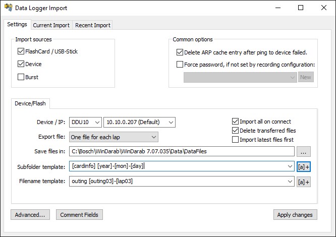
WinDarab Data Logger Import settings. The example shows Delete transferred files checked: clear it if you want to retain originals. Image: Bosch Motorsport, reproduced with permission; manufacturer import guide and original image. - Retrieve the recording: select the applicable connected source and the required fragments in the Current Import tab, choose the destination in Save files in and run the import. Wait for download, conversion and merging to finish. If you already have a supported measurement file on the PC, you can skip the device import. Import settings and process.
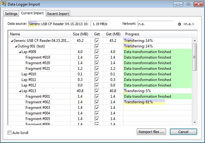
Current Import displays selected laps and fragment transfer progress; this example uses a card reader. Interface and source depend on the device and WinDarab version. Image: Bosch Motorsport, reproduced with permission; manufacturer import guide and original image. - Open and plot: choose the WinDarab button → Open measurement file or press Ctrl+E and select the imported file. Press F3 to show Channels, then drag a recorded channel such as engine speed or vehicle speed to an oscilloscope. Right-click its horizontal axis to select time or distance; distance-based analysis requires a suitable recorded or calculated distance channel. Opening files; oscilloscope axes.
- Compare: with one or more files open, use Overlay → Add; in the File Explorer, select laps or files for the overlays. Compare their coloured traces on the oscilloscope, aligning lap triggers where available. The dedicated lap-analysis view requires Expert; the data and channels must actually have been recorded. Bosch overlay instructions.
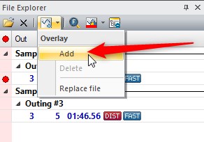
WinDarab File Explorer: use Overlay → Add to prepare an additional comparison. Image: Bosch Motorsport, reproduced with permission; manufacturer overlay guide and original image. 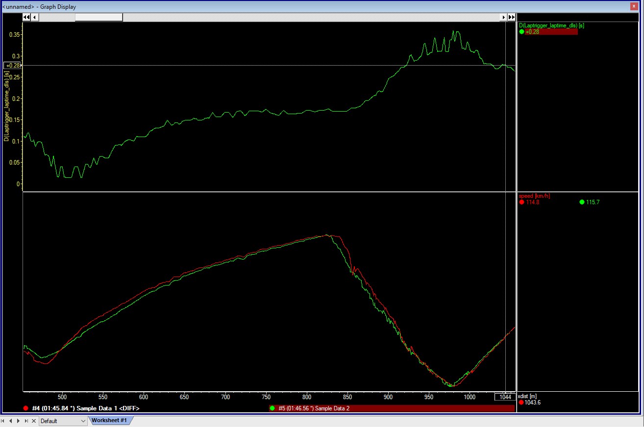
Example output: two speed traces and their lap-time difference against distance. Image: Bosch Motorsport, reproduced with permission; manufacturer overlay guide and original image. - Interpret and retain: check channel names, units, sample rates, sensor calibration and conditions before drawing conclusions. Confirm the imported file opens before removing the media or relying on the offload; save a useful WinDarab desktop layout for the next analysis.


Pinouts and cabling
The following are model-specific cavity numbers and Bosch signal labels. Confirm the exact model, options and connector orientation against the linked manufacturer documentation and the numbers moulded into the mating connector. Identify the component and viewing direction shown in each drawing; do not rely on a photograph or wire colours alone. Isolate power and check continuity before connecting. Bosch gives signal limits, supply options and configuration requirements in its manuals.
DDU 11 display logger — 26-pin connector
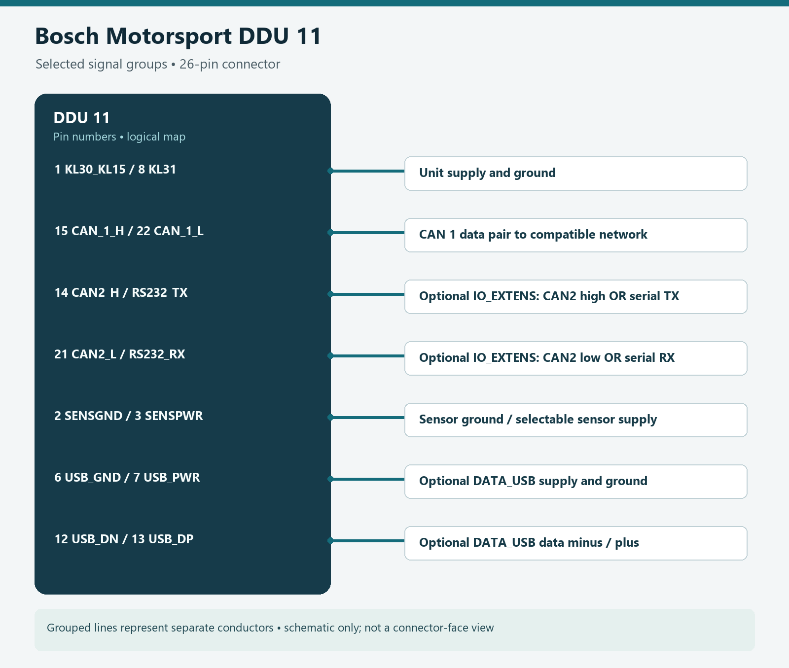
Bosch identifies the mating connector as TE Connectivity 3-1437290-7 with terminals 3-1447221-4. Assignments and upgrade status below are from the Bosch DDU 11 datasheet, pin configuration. The table is for DDU 11 only; use the manufacturer's drawing and connector numbering for orientation.
| Pin | Signal (Bosch designation) | Availability |
|---|---|---|
| 1 | KL30_KL15/UBAT | Included |
| 2 | SENSGND | Included |
| 3 | SENSPWR (5 V or UBAT switched) | Included |
| 4 | SIG2_IN | IO_EXTENS |
| 5 | SIG4_IN | IO_EXTENS |
| 6 | USB_GND | DATA_USB |
| 7 | USB_PWR | DATA_USB |
| 8 | KL31/GND | Included |
| 9 | SIG5_IN_LAPTRG | IO_EXTENS |
| 10 | SIG1_IN | IO_EXTENS |
| 11 | SIG3_IN | IO_EXTENS |
| 12 | USB_DN | DATA_USB |
| 13 | USB_DP | DATA_USB |
| 14 | CAN_2_H_RS232_TX | IO_EXTENS |
| 15 | CAN_1_H | Included |
| 16 | ETH_CHANNEL0_TXN | Included |
| 17 | ETH_CHANNEL0_TXP | Included |
| 18 | ETH_CHANNEL0_RXN | Included |
| 19 | ETH_CHANNEL0_RXP | Included |
| 20 | TIMESTMP_INOUT | Included |
| 21 | CAN_2_L_RS232_RX | IO_EXTENS |
| 22 | CAN_1_L | Included |
| 23 | ETH_CHANNEL1_TXN | Included |
| 24 | ETH_CHANNEL1_TXP | Included |
| 25 | ETH_CHANNEL1_RXN | Included |
| 26 | ETH_CHANNEL1_RXP | Included |
IO_EXTENS enables the listed analogue/digital inputs and the selectable second CAN or RS232 interface; DATA_USB enables the listed USB data-copy connections. Pins 14 and 21 are a switchable CAN 2 or RS232 pair, so configure their function for the installation. The analogue and wheel-speed input configuration and sensor supply selection are described in the datasheet and DDU 11 manual. Bosch specifies sensor supply as selectable 5 V or switched battery voltage, maximum 250 mA; check the connected sensors' requirements.
C 70 standalone logger — 55-pin motorsport connector
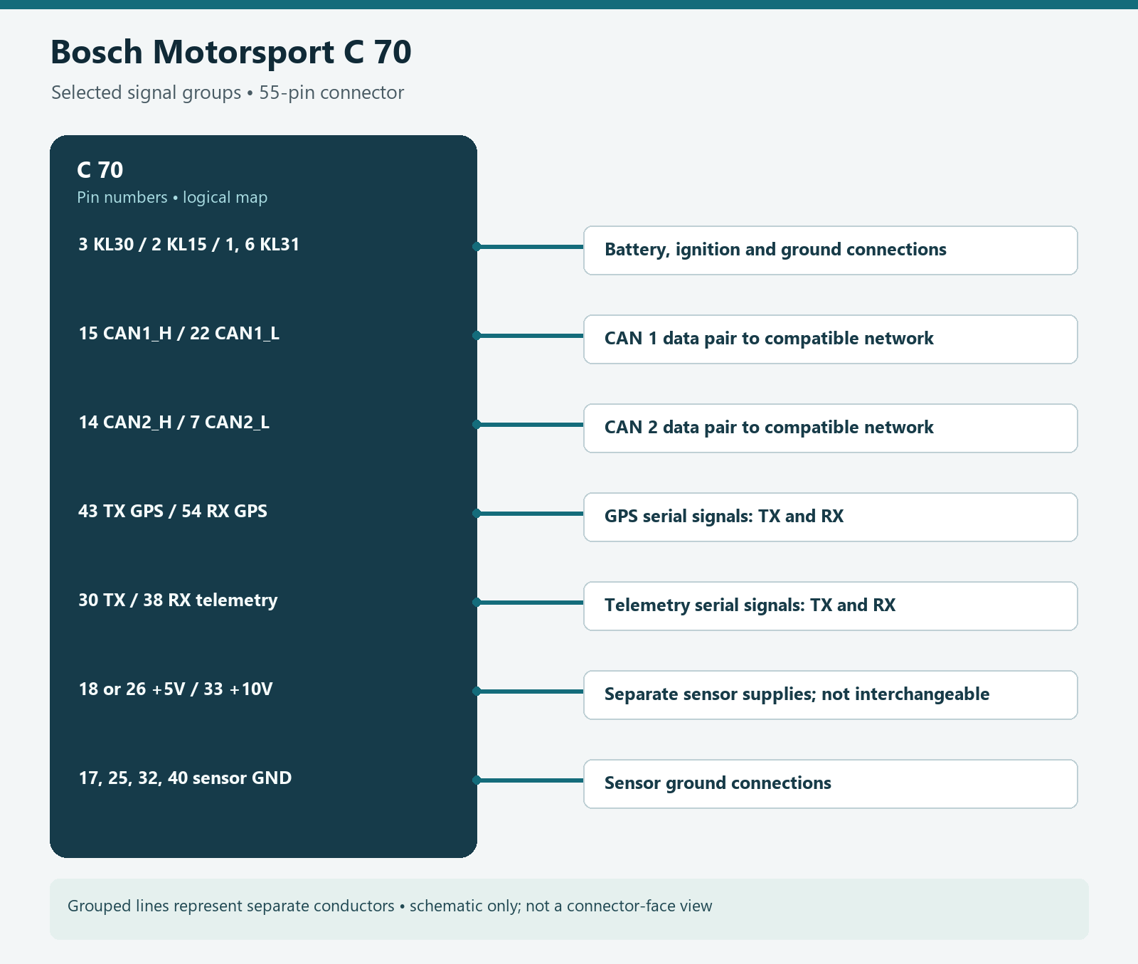
The Bosch C 70 specification identifies the logger connector as AS216-35PN and the mating connector as AS616-35SN (Bosch part F02U.000.466-01). The manufacturer’s C 70 manual gives wiring and the numbered pin configuration. Status “optional” means an applicable feature or upgrade is needed; verify the actual unit and key. Sensor supplies have distinct voltages: do not interchange them.
| Pin | Signal (Bosch designation) | Availability |
|---|---|---|
| 1 | KL_31 | Included |
| 2 | KL_15 | Included |
| 3 | KL_30 | Included |
| 4 | Rev_In_3 | Included |
| 5 | Rev_In_1 | Included |
| 6 | KL_31 | Included |
| 7 | CAN_2_L | Included |
| 8 | Ethernet_2_TXP | Included |
| 9 | Ethernet_2_TXN | Included |
| 10 | Sens_Power_12V | Included |
| 11 | Rev_In_4 | Included |
| 12 | Rev_In_2 | Included |
| 13 | Laptrigger_In | Included |
| 14 | CAN_2_H | Included |
| 15 | CAN_1_H | Included |
| 16 | Ethernet_2_RXP | Included |
| 17 | Sens_Gnd_4 | Included |
| 18 | Sens_Power_5V | Included |
| 19 | ANA_IN_3 | Included |
| 20 | ANA_IN_4 | Included |
| 21 | Time_Sync | Included |
| 22 | CAN_1_L | Included |
| 23 | Com_screen | Included |
| 24 | Ethernet_2_RXN | Included |
| 25 | Sens_Gnd_3 | Included |
| 26 | Sens_Power_5V | Included |
| 27 | ANA_IN_7 | Optional |
| 28 | ANA_IN_1 | Included |
| 29 | USB_Device_DP | Optional |
| 30 | RS232_TX_Telemetry | Included |
| 31 | Ethernet_1_TXP | Included |
| 32 | Sens_Gnd_2 | Included |
| 33 | Sens_Power_10V | Included |
| 34 | ANA_IN_8 | Optional |
| 35 | ANA_IN_10 | Optional |
| 36 | USB_Device_Gnd | Optional |
| 37 | USB_Device_DN | Optional |
| 38 | RS232_RX_Telemetry | Included |
| 39 | Ethernet_1_TXN | Included |
| 40 | Sens_Gnd_1 | Included |
| 41 | ANA_IN_11 | Optional |
| 42 | ANA_IN_9 | Optional |
| 43 | RS232_TX_GPS | Included |
| 44 | ANA_IN_16 | Optional |
| 45 | USB_Device_Power | Optional |
| 46 | Ethernet_1_RXP | Included |
| 47 | ANA_IN_12 | Optional |
| 48 | ANA_IN_6 | Optional |
| 49 | ANA_IN_2 | Included |
| 50 | ANA_IN_13 | Optional |
| 51 | ANA_IN_15 | Optional |
| 52 | Ethernet_1_RXN | Included |
| 53 | ANA_IN_5 | Optional |
| 54 | RS232_RX_GPS | Included |
| 55 | ANA_IN_14 | Optional |
Building the system
- Power: follow the specific unit's supply, grounding, fusing and startup instructions. DDU 11 and C 70 do not share a pinout. Confirm the actual loom and connector part number before applying power.
- ECU and CAN: use the correct CAN high and low pins for the chosen bus and its specified bitrate, message definition, termination and wiring. A CAN physical connection does not guarantee that the ECU transmits the desired data.
- GPS and telemetry: the C 70 has separate serial pins labelled for GPS and telemetry, but a complete system needs compatible external hardware and configuration. On DDU 11 the second interface uses the selectable CAN/RS232 pins and the IO_EXTENS option.
- Acquisition and download: select sensor types, calibrations, grounds and logging settings in RaceCon. USB and additional inputs may require upgrades. Check the data file and verify scaling in a short test before relying on the installation.
Product information and photographs
Official product pages linked above include Bosch Motorsport product photographs, specifications, manuals and current options. Photo credit: Bosch Motorsport. Consult Bosch's website legal notice for image reuse. Availability, included features and product terms may change. See also the in-car datalogging and telematics guide and live telemetry guide.