DDU 10 combines a seven-inch configurable display and internal data logging. The basic 4 GB logger records up to 100 channels at 20 Hz; FULL_LOG_1 enables up to 1,500 channels at 1 ms and FULL_LOG_2 a second 4 GB partition. DATA_USB and further inputs are options. Source: Bosch DDU 10.
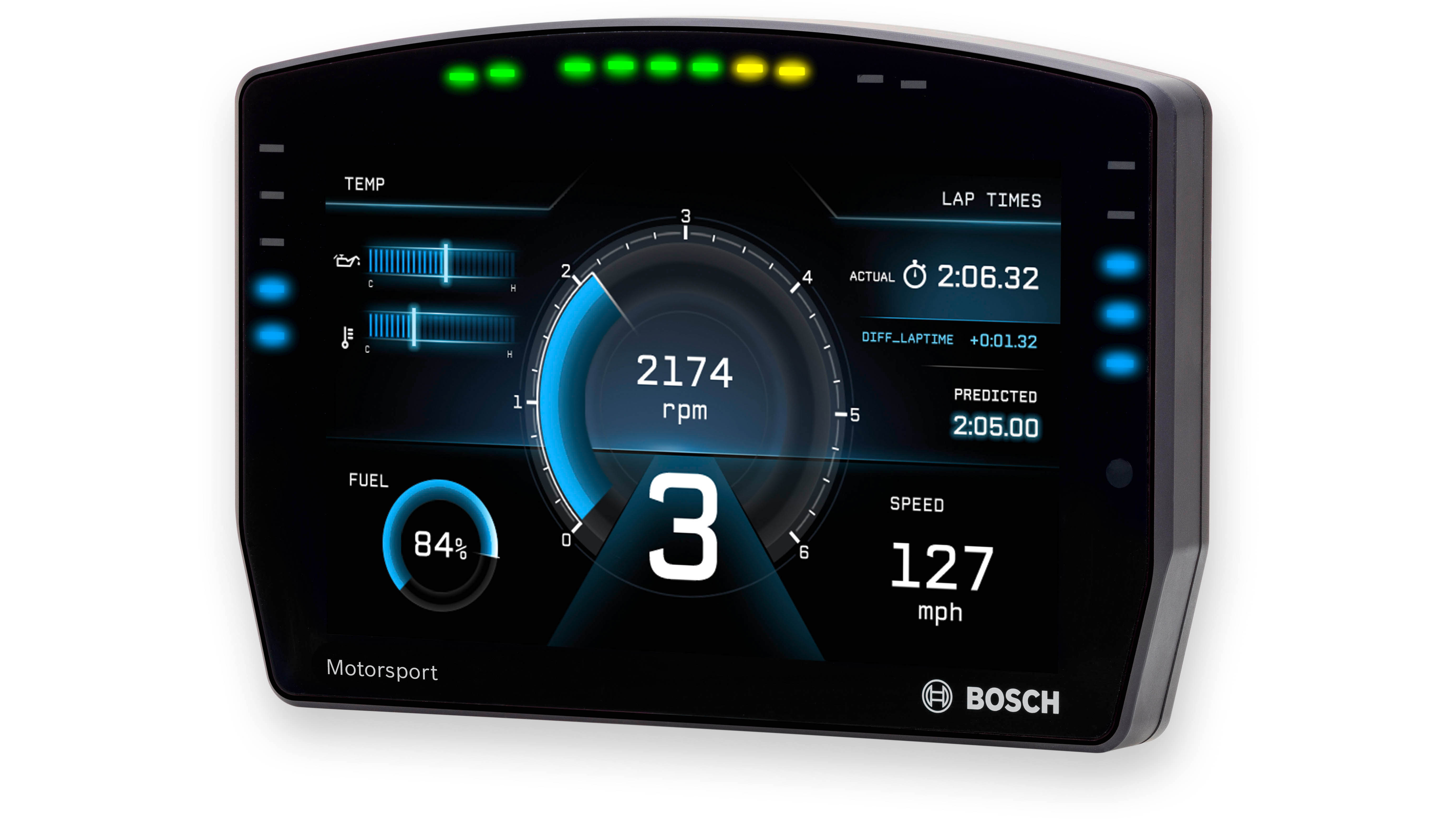
Data analysis software

Bosch lists the DDU 10 among WinDarab-supported devices. Use WinDarab V7 on a PC to examine downloaded logged channels, compare measurements and review traces. The available channels and transfer method depend on the DDU 10's configuration and enabled options. Bosch supported devices.
WinDarab V7 download, documentation and edition information. RaceCon is a separate configuration tool for compatible devices. See the Bosch Motorsport software overview.
Connector and pinout
The LIFE device connector is AS216-35PN, mating AS616-35SN; an auxiliary AS212-35PN handles further functions. The following pin tables transcribe the Bosch DDU 10 datasheet, pages 2–3. IO_EXTENS and DATA_USB are optional software upgrades. Verify the connector and hardware revision; do not apply the DDU 11 pinout to DDU 10.
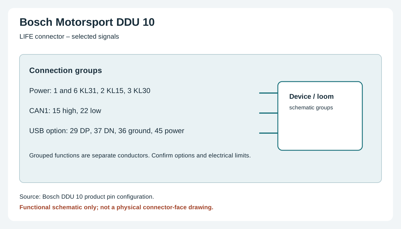
LIFE AS216-35PN — 55 positions
Analogue inputs have a switchable 3.01 kΩ pull-up according to Bosch. USB connections are for the Bosch USB stick with DATA_USB enabled.
| Pin | Bosch signal | Status / note |
|---|---|---|
| 1 | KL_31 | Included |
| 2 | KL_15 | Included |
| 3 | KL_30 | Included |
| 4 | Rev_In_3 | Included; Hall or DF11 switchable |
| 5 | Rev_In_1 | Included; Hall or DF11 switchable |
| 6 | KL_31 | Included |
| 7 | CAN_2_L | Included |
| 8 | Ethernet_2_TXP | Included |
| 9 | Ethernet_2_TXN | Included |
| 10 | Sens_Power_12V | Included; over-current protected |
| 11 | Rev_In_4 | Included; Hall or DF11 switchable |
| 12 | Rev_In_2 | Included; Hall or DF11 switchable |
| 13 | Laptrigger_In | Included |
| 14 | CAN_2_H | Included |
| 15 | CAN_1_H | Included |
| 16 | Ethernet_2_RXP | Included |
| 17 | Sens_Gnd_4 | Included; fused |
| 18 | Sens_Power 5V | Included; over-current protected |
| 19 | ANA_IN_3 | Included |
| 20 | ANA_IN_4 | Included |
| 21 | Time_Sync | Included; Bosch ECU |
| 22 | CAN_1_L | Included |
| 23 | Ethernet_screen | Included |
| 24 | Ethernet_2_RXN | Included |
| 25 | Sens_Gnd_3 | Included; fused |
| 26 | Sens_Power 5V | Included; over-current protected |
| 27 | ANA_IN_7 | IO_EXTENS |
| 28 | ANA_IN_1 | Included |
| 29 | USB_Device_DP | DATA_USB |
| 30 | RS232_TX_Telemetry | Included |
| 31 | Ethernet_1_TXP | Included |
| 32 | Sens_Gnd_2 | Included; fused |
| 33 | Sens_Power_10V | Included; over-current protected |
| 34 | ANA_IN_8 | IO_EXTENS |
| 35 | ANA_IN_10 | IO_EXTENS |
| 36 | USB_Device_Gnd | DATA_USB |
| 37 | USB_Device_DN | DATA_USB |
| 38 | RS232_RX_Telemetry | Included |
| 39 | Ethernet_1_TXN | Included |
| 40 | Sens_Gnd_1 | Included; fused |
| 41 | ANA_IN_11 | IO_EXTENS |
| 42 | ANA_IN_9 | Optional (source does not give option number) |
| 43 | RS232_TX_GPS | Included |
| 44 | ANA_IN_16 | IO_EXTENS |
| 45 | USB_Device_Power | DATA_USB |
| 46 | Ethernet_1_RXP | Included |
| 47 | ANA_IN_12 | IO_EXTENS |
| 48 | ANA_IN_6 | IO_EXTENS |
| 49 | ANA_IN_2 | Included |
| 50 | ANA_IN_13 | IO_EXTENS |
| 51 | ANA_IN_15 | IO_EXTENS |
| 52 | Ethernet_1_RXN | Included |
| 53 | ANA_IN_5 | IO_EXTENS |
| 54 | RS232_RX_GPS | Included |
| 55 | ANA_IN_14 | IO_EXTENS |
Auxiliary AS212-35PN — 22 positions
Mating connector AS612-35SN. IO_EXTENS adds CAN 3 and CAN 4.
| Pin | Bosch signal | Status / note |
|---|---|---|
| 1 | Unused | Unused |
| 2 | Unused | Unused |
| 3 | Unused | Unused |
| 4 | Unused | Unused |
| 5 | Unused | Unused |
| 6 | Unused | Unused |
| 7 | Unused | Unused |
| 8 | Unused | Unused |
| 9 | Ethernet_3_TXP | Included |
| 10 | Ethernet_3_RXP | Included |
| 11 | Ethernet_3_RXN | Included |
| 12 | CAN_4_H | IO_EXTENS |
| 13 | Unused | Unused |
| 14 | Unused | Unused |
| 15 | Unused | Unused |
| 16 | Unused | Unused |
| 17 | Unused | Unused |
| 18 | Ethernet_screen | Included |
| 19 | Ethernet_3_TXN | Included |
| 20 | CAN_4_L | IO_EXTENS |
| 21 | CAN_3_H | IO_EXTENS |
| 22 | CAN_3_L | IO_EXTENS |
Installation and related information
Confirm the precise model, hardware revision, enabled options and manufacturer's wiring diagram before connecting. Use correct power protection, sensor limits and the chosen ECU protocol; a compatible connector does not guarantee compatible data. Configure in the appropriate Bosch software and verify a short recording or connection. See the Bosch Motorsport manufacturer overview.