C 60 is a compact legacy logger. Bosch describes 2 GB storage, an 8–18 V supply, Ethernet/CAN integration and optional extra inputs, USB and CCP master; up to 26 analogue and four digital inputs depend on enabled features. Source: Bosch C 60 datasheet.

Data analysis software

Bosch lists the C 60 among WinDarab-supported devices. Use WinDarab V7 on a PC to examine downloaded logged channels, compare measurements and review traces. The available channels and transfer method depend on the C 60's configuration and enabled options. Bosch supported devices.
WinDarab V7 download, documentation and edition information. RaceCon is a separate configuration tool for compatible devices. See the Bosch Motorsport software overview.
Connectors and wiring
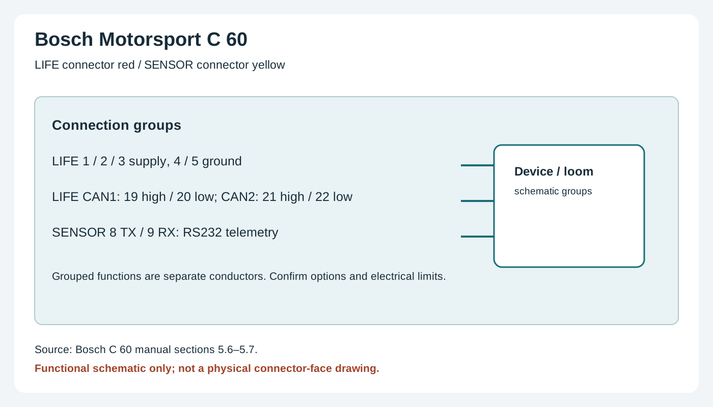
C 60 uses two keyed 41-way connectors: LIFE (red) ASDD212-41PN and SENSOR (yellow) ASDD212-41PA. The tables below transcribe the older manual only; Bosch's later datasheet differs on LIFE pins 23–26 and Ethernet channel naming. Neither document establishes which hardware or part-number revisions use each map. Do not assume the older map applies to your unit; obtain the Bosch pinout for its exact part number and revision before wiring. Tables below follow the Bosch C 60 manual, sections 5.6–5.7. Some sensor inputs require an upgrade. Confirm the actual hardware revision, keyed connector, drawing view and cavity numbers before wiring. C 70's 55-pin table does not apply.
LIFE connector, red ASDD212-41PN — older manual
Source discrepancy: The older manual lists LIFE pins 23–26 as not connected. The 2019 Bosch datasheet, page 2, instead lists 23 USB power (500 mA), 24 USB data plus, 25 USB data minus, and 26 USB ground. USB also requires the relevant software upgrade. Verify the unit-specific Bosch wiring before connecting these pins; the documents do not establish the affected serial numbers or revision change. The older manual numbers Ethernet groups 1–3, while the 2019 datasheet names them channels 0–2 and repeats channel 0 in some descriptions; confirm the intended port for the unit rather than relying on channel labels alone.
| Pin | Bosch signal |
|---|---|
| 1 | UBATT |
| 2 | Switched positive KL15 |
| 3 | Switched positive KL15 |
| 4 | Unit ground |
| 5 | Unit ground |
| 6 | ETH1_TX+ |
| 7 | ETH1_TX− |
| 8 | ETH1_RX+ |
| 9 | ETH1_RX− |
| 10 | ETH_SCR |
| 11 | ETH2_TX+ |
| 12 | ETH2_TX− |
| 13 | ETH2_RX+ |
| 14 | ETH2_RX− |
| 15 | ETH3_TX+ |
| 16 | ETH3_TX− |
| 17 | ETH3_RX+ |
| 18 | ETH3_RX− |
| 19 | CAN1_H |
| 20 | CAN1_L |
| 21 | CAN2_H |
| 22 | CAN2_L |
| 23 | Not connected in older manual; 2019 datasheet assigns USB power (500 mA). See discrepancy above. |
| 24 | Not connected in older manual; 2019 datasheet assigns USB data plus. See discrepancy above. |
| 25 | Not connected in older manual; 2019 datasheet assigns USB data minus. See discrepancy above. |
| 26 | Not connected in older manual; 2019 datasheet assigns USB ground. See discrepancy above. |
| 27 | SENSPWR5_1 |
| 28 | SENSGND_1 |
| 29 | TimeSync |
| 30 | LS_GND_1 |
| 31 | LS_SWITCH_1 |
| 32 | LS_SWITCH_2 |
| 33 | LS_SWITCH_3 |
| 34 | LS_SWITCH_4 |
| 35 | LS_GND_2 |
| 36 | ANA01 |
| 37 | ANA02 |
| 38 | ANA03 |
| 39 | ANA04 |
| 40 | ANA05 |
| 41 | ANA06 |
SENSOR connector, yellow ASDD212-41PA
| Pin | Bosch signal |
|---|---|
| 1 | UBATT_FUSE1 |
| 2 | SENSPWR10_1 |
| 3 | SENSPWR5_2 |
| 4 | SENSPWR5_3 |
| 5 | SENSPWR5_4 |
| 6 | SENSGND_2 |
| 7 | SENSGND_3 |
| 8 | RS232_1_TX |
| 9 | RS232_1_RX |
| 10 | RS232_2_TX |
| 11 | RS232_2_RX |
| 12 | RS232_GND |
| 13 | REV1_P |
| 14 | REV1_M |
| 15 | REV2_P |
| 16 | REV2_M |
| 17 | REV3_P |
| 18 | REV3_M |
| 19 | REV4_P |
| 20 | REV4_M |
| 21 | ANA07 |
| 22 | ANA08 |
| 23 | ANA09 |
| 24 | ANA10 |
| 25 | ANA11 |
| 26 | ANA12 |
| 27 | ANA13 |
| 28 | ANA14 |
| 29 | ANA15 |
| 30 | ANA16 |
| 31 | ANA17 |
| 32 | ANA18 |
| 33 | ANA19 |
| 34 | ANA20 |
| 35 | ANA21 |
| 36 | ANA22 |
| 37 | ANA23 |
| 38 | ANA24 |
| 39 | ANA25 |
| 40 | ANA26 |
| 41 | LAP_TRIG |
Installation and related information
Confirm the precise model, hardware revision, enabled options and manufacturer's wiring diagram before connecting. Use correct power protection, sensor limits and the chosen ECU protocol; a compatible connector does not guarantee compatible data. Configure in the appropriate Bosch software and verify a short recording or connection. See the Bosch Motorsport manufacturer overview.