Removed text is struck through; added text is highlighted.
Why a film replaced the wire
A hot-film meter is the same thermal idea as a hot wire: a heated element is held above the temperature of the incoming air, and the heat the air carries away is the mass flow. The element is a resistive film on a ceramic or silicon substrate instead of a free platinum wire. It is less fragile, it collects less of the kind of deposit that forces a burn-off cycle, and the circuit can be printed on the same substrate as the element. One description of the foil grid holds it about 75 °C (167 °F) above the surrounding air. That offset is this construction. It is separate from the 100 °C wire offset and from the 200 °C wire description.
The housing is still a measuring tube, or a plug-in insert in someone else’s tube. Only a sample of the air passes the film. The relationship between that sample and the mass in the whole duct is fixed when the meter is calibrated. Moving the insert into another tube, or damaging the sample passage, keeps a healthy-looking voltage and reports the wrong mass.
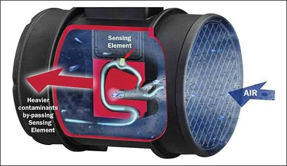
Air enters the tube on the right. Heavier particles tend to carry straight on. The sensing element sits in a curved sample passage taken off that main flow.
Inside the insert the sample turns across the element and leaves by the measuring outlet. A second outlet lets the heavier particles leave before they reach the film.
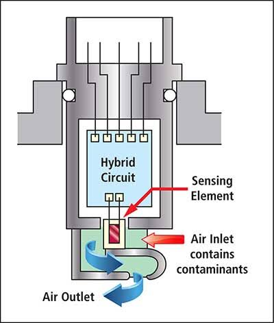
The hybrid sits directly above the film. The sample enters beside the element and leaves through the air outlet. Dust that stays in that sample still reaches the film.
Thick-film bridge
The Bosch HFM 2 prints the resistors onto ceramic: an air-temperature resistor, a heater, a platinum sensor film, and a trimmer. Heater and sensor film are in thermal contact. The heater holds the film a constant temperature above the incoming air. The air-temperature resistor and the trimmer form one arm of a bridge, the sensor film the other, and the voltage across the bridge is the signal. There is no burn-off. The control unit does not need a cleaning cycle, because the film is much less sensitive to contamination than a hot wire.
Four curves cover 10–350, 10–480, 12–640 and 20–1080 kg/h, each ±4 % of the measured value, on a 0 to 5 V output from a 14 V supply. The plug has four pins: ground, signal negative, supply, signal positive. The measuring venturi is inclined at least 5° from horizontal so water cannot pool on the film, and the intake air has to come through a filter.
Micromechanical film, and direction
The Bosch HFM 5 puts a micromechanical element in a small flow passage on a hybrid. The heated element gives up heat to the air. Temperature sensors on the membrane see which side is hotter. Flow from the filter toward the engine heats the downstream side. Flow backwards, which is what an intake pulse does on a four-cylinder and on many diesels, heats the other side. The hybrid reports both the mass and the direction, so a reverse pulse is not counted as more air going into the engine.
Five production housings cover ranges from 8–370 kg/h up to 15–1000 kg/h, each with its own voltage curve. The same 3 V is a modest flow on the smallest curve and a much larger flow on the largest. Supply is 8 to 17 V, signal is 0 to 5 V, current is under 0.1 A, and relative accuracy is within 3 %. Response to a flow step reaches 63 % within 15 ms. Most versions include an intake-air temperature sensor, nominal 2.00 kΩ at 25 °C, on pin 1. Version 4, part 0 280 218 008, has no temperature sensor. Pins 2, 3, 4 and 5 are supply, signal ground, 5 V reference and the mass signal. A later listing of 0 281 002 421 extends the range to −50 to 1200 kg/h. That is a different calibration from the 15 to 1000 kg/h column, and the voltage table for characteristic 5 is printed under a neighbouring part number. Use the number on the housing.
The HFM 7 keeps the film and adds a deflection bypass: a deflection edge, fins and vortex steps, with a path that lets water and particles leave before they reach the chip. The insert and the tube are supplied and calibrated as one assembly. Opening that assembly, or copying the film without the bypass, is a meter whose sample is no longer the sample it was calibrated on. Idle, economy, emissions and throttle response are where that shows up.
Frequency instead of voltage
Some films produce a square wave rather than a rising analogue voltage. The mass is the frequency of that wave, and whether frequency rises or falls with flow is part of the calibration.
AC Rochester hot-film meters, from 1984 on the Buick turbo 3.8 and also on the Chevrolet 2.8 and the GM 3.0 and 3.8, run from about 32 Hz at idle to about 150 Hz at wide-open throttle. A 2.8 litre example is about 32 Hz at idle and about 75 Hz at 3500 rpm. The signal, read as a voltage at idle on the Delco meters, sits near 2.5 V and must stay still when the housing is tapped. In 1990 most GM engines left the mass-air meter for speed-density. The Buick 3.3 and 3.8 moved to a Hitachi film whose frequency is much higher: about 2.9 kHz at idle and about 5.0 kHz at 3500 rpm on a 3800. A scan tool may show the same signal as grams per second, about 4 to 8 g/s at idle and 100 to 240 g/s at wide open. GM codes 33 and 34 are frequency too high and too low on the multiport engines. Code 36 belongs to the Bosch hot-wire burn-off. It does not belong to these films.
The Pierburg meter on the 1.6 HDi and TDCi also uses frequency, and the frequency falls as flow rises. Ignition on, engine stopped, the setpoint is 5000 Hz ± 10 Hz, and the rectangle swings to about 12 V. Opening the throttle lengthens the pulses. Applying the GM “frequency should rise” test to this sensor condemns a working meter. The pinout, the temperature resistances and the vehicle list are on the Pierburg frequency page. Ford mass-air codes 26, 56, 66 and 76 are a third system again. They are listed with the measurement notes on hot wire, hot film, vane and Karman.
A programmable curve
Siemens VDO’s SIMAF is a hot-film bridge: one resistor tracks air temperature, the flow resistor is held a fixed temperature above it, and the current is read across a fixed resistor. A programmable ROM, up to nine points, turns that into an analogue voltage, a ratiometric voltage, or a frequency. Reverse-flow compensation is part of the channel geometry and stays within ±5 % for modulation under 200 %. Sensor tolerance is ±2 %. The same family can therefore wear the curve of more than one control unit. Two SIMAF sensors are interchangeable only when they were programmed for the same curve.
The Siemens 20.3855 is a fixed hot-film curve, 8 to 550 kg/h at nominal 12 V, collapsing to 8 to 140 kg/h if the supply is only 7.5 to 9 V. The maf2maf converter exists to turn that voltage into an HFM 5 curve. Its 12 V feed has to come from an ignition relay. The 20.3855 peaks near 1 A at switch-on, and the HFM 5 supply pin inside a control unit is rated for about a tenth of that.
The PMA1000 is a film module for a customer’s own housing, with the heater on a solid thermal base rather than a thin membrane, a thermopile for temperature, and up to 16 calibration points. It detects reverse flow. Heating current is adjustable within ±20 % of the target curve before the points are programmed.
What fails, and what a swap does
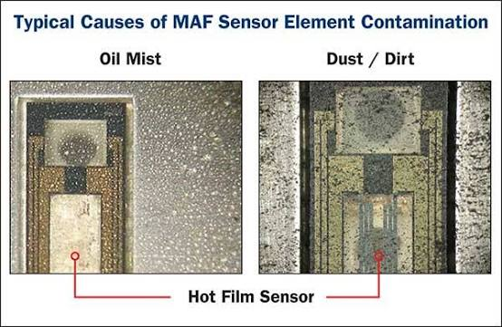
The same style of film, coated with oil mist on the left and with dust on the right. Either layer cuts the heat leaving the element, so the meter reports less mass than is flowing.
Oil and dust on the film reduce heat transfer, so reported mass falls and open-loop fuel goes lean. Water pooled in a level measuring tube does the same, intermittently, which is why the HFM 2 venturi is inclined. The usual failure of a swapped film is a wrong curve: the voltage is clean, the frequency is stable, and the control unit injects for a mass the engine does not have. On a diesel that wrong mass also moves the EGR rate. The 1.9 TDI comparison of a Bosch film, a Pierburg film and a Mercedes CDI film is the worked example, on Volkswagen TDI air-mass measurement.
Rendered revisions
Open each version to inspect formatting, tables and photographs.
Revision 2: Hot-film mass airflow sensors
Why a film replaced the wire
A hot-film meter is the same thermal idea as a hot wire: a heated element is held above the temperature of the incoming air, and the heat the air carries away is the mass flow. The element is a resistive film on a ceramic or silicon substrate instead of a free platinum wire. It is less fragile, it collects less of the kind of deposit that forces a burn-off cycle, and the circuit can be printed on the same substrate as the element. One description of the foil grid holds it about 75 °C (167 °F) above the surrounding air. That offset is this construction. It is separate from the 100 °C wire offset and from the 200 °C wire description.
The housing is still a measuring tube, or a plug-in insert in someone else’s tube. Only a sample of the air passes the film. The relationship between that sample and the mass in the whole duct is fixed when the meter is calibrated. Moving the insert into another tube, or damaging the sample passage, keeps a healthy-looking voltage and reports the wrong mass.
Air enters the tube on the right. Heavier particles tend to carry straight on. The sensing element sits in a curved sample passage taken off that main flow.Inside the insert the sample turns across the element and leaves by the measuring outlet. A second outlet lets the heavier particles leave before they reach the film.The hybrid sits directly above the film. The sample enters beside the element and leaves through the air outlet. Dust that stays in that sample still reaches the film.
Thick-film bridge
The Bosch HFM 2 prints the resistors onto ceramic: an air-temperature resistor, a heater, a platinum sensor film, and a trimmer. Heater and sensor film are in thermal contact. The heater holds the film a constant temperature above the incoming air. The air-temperature resistor and the trimmer form one arm of a bridge, the sensor film the other, and the voltage across the bridge is the signal. There is no burn-off. The control unit does not need a cleaning cycle, because the film is much less sensitive to contamination than a hot wire.
Four curves cover 10–350, 10–480, 12–640 and 20–1080 kg/h, each ±4 % of the measured value, on a 0 to 5 V output from a 14 V supply. The plug has four pins: ground, signal negative, supply, signal positive. The measuring venturi is inclined at least 5° from horizontal so water cannot pool on the film, and the intake air has to come through a filter.
Micromechanical film, and direction
The Bosch HFM 5 puts a micromechanical element in a small flow passage on a hybrid. The heated element gives up heat to the air. Temperature sensors on the membrane see which side is hotter. Flow from the filter toward the engine heats the downstream side. Flow backwards, which is what an intake pulse does on a four-cylinder and on many diesels, heats the other side. The hybrid reports both the mass and the direction, so a reverse pulse is not counted as more air going into the engine.
Five production housings cover ranges from 8–370 kg/h up to 15–1000 kg/h, each with its own voltage curve. The same 3 V is a modest flow on the smallest curve and a much larger flow on the largest. Supply is 8 to 17 V, signal is 0 to 5 V, current is under 0.1 A, and relative accuracy is within 3 %. Response to a flow step reaches 63 % within 15 ms. Most versions include an intake-air temperature sensor, nominal 2.00 kΩ at 25 °C, on pin 1. Version 4, part 0 280 218 008, has no temperature sensor. Pins 2, 3, 4 and 5 are supply, signal ground, 5 V reference and the mass signal. A later listing of 0 281 002 421 extends the range to −50 to 1200 kg/h. That is a different calibration from the 15 to 1000 kg/h column, and the voltage table for characteristic 5 is printed under a neighbouring part number. Use the number on the housing.
The HFM 7 keeps the film and adds a deflection bypass: a deflection edge, fins and vortex steps, with a path that lets water and particles leave before they reach the chip. The insert and the tube are supplied and calibrated as one assembly. Opening that assembly, or copying the film without the bypass, is a meter whose sample is no longer the sample it was calibrated on. Idle, economy, emissions and throttle response are where that shows up.
Frequency instead of voltage
Some films produce a square wave rather than a rising analogue voltage. The mass is the frequency of that wave, and whether frequency rises or falls with flow is part of the calibration.
AC Rochester hot-film meters, from 1984 on the Buick turbo 3.8 and also on the Chevrolet 2.8 and the GM 3.0 and 3.8, run from about 32 Hz at idle to about 150 Hz at wide-open throttle. A 2.8 litre example is about 32 Hz at idle and about 75 Hz at 3500 rpm. The signal, read as a voltage at idle on the Delco meters, sits near 2.5 V and must stay still when the housing is tapped. In 1990 most GM engines left the mass-air meter for speed-density. The Buick 3.3 and 3.8 moved to a Hitachi film whose frequency is much higher: about 2.9 kHz at idle and about 5.0 kHz at 3500 rpm on a 3800. A scan tool may show the same signal as grams per second, about 4 to 8 g/s at idle and 100 to 240 g/s at wide open. GM codes 33 and 34 are frequency too high and too low on the multiport engines. Code 36 belongs to the Bosch hot-wire burn-off. It does not belong to these films.
The Pierburg meter on the 1.6 HDi and TDCi also uses frequency, and the frequency falls as flow rises. Ignition on, engine stopped, the setpoint is 5000 Hz ± 10 Hz, and the rectangle swings to about 12 V. Opening the throttle lengthens the pulses. Applying the GM “frequency should rise” test to this sensor condemns a working meter. The pinout, the temperature resistances and the vehicle list are on the Pierburg frequency page. Ford mass-air codes 26, 56, 66 and 76 are a third system again. They are listed with the measurement notes on hot wire, hot film, vane and Karman.
A programmable curve
Siemens VDO’s SIMAF is a hot-film bridge: one resistor tracks air temperature, the flow resistor is held a fixed temperature above it, and the current is read across a fixed resistor. A programmable ROM, up to nine points, turns that into an analogue voltage, a ratiometric voltage, or a frequency. Reverse-flow compensation is part of the channel geometry and stays within ±5 % for modulation under 200 %. Sensor tolerance is ±2 %. The same family can therefore wear the curve of more than one control unit. Two SIMAF sensors are interchangeable only when they were programmed for the same curve.
The Siemens 20.3855 is a fixed hot-film curve, 8 to 550 kg/h at nominal 12 V, collapsing to 8 to 140 kg/h if the supply is only 7.5 to 9 V. The maf2maf converter exists to turn that voltage into an HFM 5 curve. Its 12 V feed has to come from an ignition relay. The 20.3855 peaks near 1 A at switch-on, and the HFM 5 supply pin inside a control unit is rated for about a tenth of that.
The PMA1000 is a film module for a customer’s own housing, with the heater on a solid thermal base rather than a thin membrane, a thermopile for temperature, and up to 16 calibration points. It detects reverse flow. Heating current is adjustable within ±20 % of the target curve before the points are programmed.
What fails, and what a swap does
The same style of film, coated with oil mist on the left and with dust on the right. Either layer cuts the heat leaving the element, so the meter reports less mass than is flowing.
Oil and dust on the film reduce heat transfer, so reported mass falls and open-loop fuel goes lean. Water pooled in a level measuring tube does the same, intermittently, which is why the HFM 2 venturi is inclined. The usual failure of a swapped film is a wrong curve: the voltage is clean, the frequency is stable, and the control unit injects for a mass the engine does not have. On a diesel that wrong mass also moves the EGR rate. The 1.9 TDI comparison of a Bosch film, a Pierburg film and a Mercedes CDI film is the worked example, on Volkswagen TDI air-mass measurement.
Revision 2: Hot-film mass airflow sensors
Why a film replaced the wire
A hot-film meter is the same thermal idea as a hot wire: a heated element is held above the temperature of the incoming air, and the heat the air carries away is the mass flow. The element is a resistive film on a ceramic or silicon substrate instead of a free platinum wire. It is less fragile, it collects less of the kind of deposit that forces a burn-off cycle, and the circuit can be printed on the same substrate as the element. One description of the foil grid holds it about 75 °C (167 °F) above the surrounding air. That offset is this construction. It is separate from the 100 °C wire offset and from the 200 °C wire description.
The housing is still a measuring tube, or a plug-in insert in someone else’s tube. Only a sample of the air passes the film. The relationship between that sample and the mass in the whole duct is fixed when the meter is calibrated. Moving the insert into another tube, or damaging the sample passage, keeps a healthy-looking voltage and reports the wrong mass.
Air enters the tube on the right. Heavier particles tend to carry straight on. The sensing element sits in a curved sample passage taken off that main flow.Inside the insert the sample turns across the element and leaves by the measuring outlet. A second outlet lets the heavier particles leave before they reach the film.The hybrid sits directly above the film. The sample enters beside the element and leaves through the air outlet. Dust that stays in that sample still reaches the film.
Thick-film bridge
The Bosch HFM 2 prints the resistors onto ceramic: an air-temperature resistor, a heater, a platinum sensor film, and a trimmer. Heater and sensor film are in thermal contact. The heater holds the film a constant temperature above the incoming air. The air-temperature resistor and the trimmer form one arm of a bridge, the sensor film the other, and the voltage across the bridge is the signal. There is no burn-off. The control unit does not need a cleaning cycle, because the film is much less sensitive to contamination than a hot wire.
Four curves cover 10–350, 10–480, 12–640 and 20–1080 kg/h, each ±4 % of the measured value, on a 0 to 5 V output from a 14 V supply. The plug has four pins: ground, signal negative, supply, signal positive. The measuring venturi is inclined at least 5° from horizontal so water cannot pool on the film, and the intake air has to come through a filter.
Micromechanical film, and direction
The Bosch HFM 5 puts a micromechanical element in a small flow passage on a hybrid. The heated element gives up heat to the air. Temperature sensors on the membrane see which side is hotter. Flow from the filter toward the engine heats the downstream side. Flow backwards, which is what an intake pulse does on a four-cylinder and on many diesels, heats the other side. The hybrid reports both the mass and the direction, so a reverse pulse is not counted as more air going into the engine.
Five production housings cover ranges from 8–370 kg/h up to 15–1000 kg/h, each with its own voltage curve. The same 3 V is a modest flow on the smallest curve and a much larger flow on the largest. Supply is 8 to 17 V, signal is 0 to 5 V, current is under 0.1 A, and relative accuracy is within 3 %. Response to a flow step reaches 63 % within 15 ms. Most versions include an intake-air temperature sensor, nominal 2.00 kΩ at 25 °C, on pin 1. Version 4, part 0 280 218 008, has no temperature sensor. Pins 2, 3, 4 and 5 are supply, signal ground, 5 V reference and the mass signal. A later listing of 0 281 002 421 extends the range to −50 to 1200 kg/h. That is a different calibration from the 15 to 1000 kg/h column, and the voltage table for characteristic 5 is printed under a neighbouring part number. Use the number on the housing.
The HFM 7 keeps the film and adds a deflection bypass: a deflection edge, fins and vortex steps, with a path that lets water and particles leave before they reach the chip. The insert and the tube are supplied and calibrated as one assembly. Opening that assembly, or copying the film without the bypass, is a meter whose sample is no longer the sample it was calibrated on. Idle, economy, emissions and throttle response are where that shows up.
Frequency instead of voltage
Some films produce a square wave rather than a rising analogue voltage. The mass is the frequency of that wave, and whether frequency rises or falls with flow is part of the calibration.
AC Rochester hot-film meters, from 1984 on the Buick turbo 3.8 and also on the Chevrolet 2.8 and the GM 3.0 and 3.8, run from about 32 Hz at idle to about 150 Hz at wide-open throttle. A 2.8 litre example is about 32 Hz at idle and about 75 Hz at 3500 rpm. The signal, read as a voltage at idle on the Delco meters, sits near 2.5 V and must stay still when the housing is tapped. In 1990 most GM engines left the mass-air meter for speed-density. The Buick 3.3 and 3.8 moved to a Hitachi film whose frequency is much higher: about 2.9 kHz at idle and about 5.0 kHz at 3500 rpm on a 3800. A scan tool may show the same signal as grams per second, about 4 to 8 g/s at idle and 100 to 240 g/s at wide open. GM codes 33 and 34 are frequency too high and too low on the multiport engines. Code 36 belongs to the Bosch hot-wire burn-off. It does not belong to these films.
The Pierburg meter on the 1.6 HDi and TDCi also uses frequency, and the frequency falls as flow rises. Ignition on, engine stopped, the setpoint is 5000 Hz ± 10 Hz, and the rectangle swings to about 12 V. Opening the throttle lengthens the pulses. Applying the GM “frequency should rise” test to this sensor condemns a working meter. The pinout, the temperature resistances and the vehicle list are on the Pierburg frequency page. Ford mass-air codes 26, 56, 66 and 76 are a third system again. They are listed with the measurement notes on hot wire, hot film, vane and Karman.
A programmable curve
Siemens VDO’s SIMAF is a hot-film bridge: one resistor tracks air temperature, the flow resistor is held a fixed temperature above it, and the current is read across a fixed resistor. A programmable ROM, up to nine points, turns that into an analogue voltage, a ratiometric voltage, or a frequency. Reverse-flow compensation is part of the channel geometry and stays within ±5 % for modulation under 200 %. Sensor tolerance is ±2 %. The same family can therefore wear the curve of more than one control unit. Two SIMAF sensors are interchangeable only when they were programmed for the same curve.
The Siemens 20.3855 is a fixed hot-film curve, 8 to 550 kg/h at nominal 12 V, collapsing to 8 to 140 kg/h if the supply is only 7.5 to 9 V. The maf2maf converter exists to turn that voltage into an HFM 5 curve. Its 12 V feed has to come from an ignition relay. The 20.3855 peaks near 1 A at switch-on, and the HFM 5 supply pin inside a control unit is rated for about a tenth of that.
The PMA1000 is a film module for a customer’s own housing, with the heater on a solid thermal base rather than a thin membrane, a thermopile for temperature, and up to 16 calibration points. It detects reverse flow. Heating current is adjustable within ±20 % of the target curve before the points are programmed.
What fails, and what a swap does
The same style of film, coated with oil mist on the left and with dust on the right. Either layer cuts the heat leaving the element, so the meter reports less mass than is flowing.
Oil and dust on the film reduce heat transfer, so reported mass falls and open-loop fuel goes lean. Water pooled in a level measuring tube does the same, intermittently, which is why the HFM 2 venturi is inclined. The usual failure of a swapped film is a wrong curve: the voltage is clean, the frequency is stable, and the control unit injects for a mass the engine does not have. On a diesel that wrong mass also moves the EGR rate. The 1.9 TDI comparison of a Bosch film, a Pierburg film and a Mercedes CDI film is the worked example, on Volkswagen TDI air-mass measurement.