MoTeC makes in-car data acquisition systems for motorsport, from a display that can be upgraded to log, to a separate enclosed logger used with a dash or power distribution system. The displayed value and the stored value are separate: a car can show ECU data without the display having logging enabled. MoTeC's display logger range, with product photographs and enclosed logger range, with photographs identify the equipment.


Individual model references
Each page provides model-specific specifications, the manufacturer’s connector assignment, a wiring example and a product photograph. Confirm part number and enabled options.
- MoTeC C125 — part #18065.
- MoTeC C127 — part #18069.
- MoTeC C1212 — part #18054.
- MoTeC C185 — part #18068.
- MoTeC C187 — part #18072.
- MoTeC C1812 — part #18053.
- MoTeC CDL3 — part #18022.
- MoTeC L120 — part #18039.
- MoTeC L120 USB — part #18045.
- MoTeC L180 — part #18047.
Display and logger families
| Family | Format | Logging and distinctions |
|---|---|---|
| C125, C127, C1212 | Colour displays, approximately 5, 7 and 12 inches respectively | The C12x Race displays come without logging as standard; the 120 MB internal logging upgrade makes them loggers. USB logging is another option, with the internal upgrade required. Race Logging Kits include the internal logging upgrade; Race Display Kits do not. I/O, Pro Analysis, Display Creator and telemetry are separate options. |
| C185, C187, C1812 | Professional colour display loggers in approximately 5, 7 and 12 inch sizes | C18x units include 250 MB internal logging. The USB upgrade also increases internal storage to 500 MB. Pro Analysis, additional I/O, advanced functions, Display Creator and telemetry are separately listed upgrades; verify the actual unit's enabled options. |
| CDL3 | Monochrome display logger | Listed alongside the colour display loggers; check kit and upgrade contents against the MoTeC comparison. |
| L120 and L120 USB | Enclosed units without a display | The USB version #18045 includes 120 MB internal and USB logging. For #18039, MoTeC's individual product page describes 120 MB logging as a feature, while its comparison table lists 0 MB by default and 120 MB optional. Confirm the exact serial number and logging entitlement with MoTeC or a dealer before purchase. |
| L180 | Enclosed logger without a display | 250 MB internal logging; optional upgrade adds USB and raises internal memory to 500 MB. Pro Analysis, additional I/O, telemetry and advanced functions are options. |
The display comparison quotes maximum logging rates of 500 samples per second for the C12x and 1,000 for the C18x. The enclosed logger comparison gives the corresponding maxima for L120 and L180. These are logger settings, not a promise that an ECU transmits every channel at that rate.
Inputs, integration and installation
The log can combine values supplied by the engine ECU with other channels, subject to the logger's configured communications and fitted sensors. MoTeC lists two configurable CAN buses and RS232 connections on the L120, and four configurable CAN buses plus RS232 on the L180. L120 analogue voltage and temperature inputs require its I/O upgrade; L180 provides ten analogue voltage and four analogue temperature inputs as standard, with more available by upgrade. E816 and E888 expanders can add I/O; L180 supports VIM and SVIM expanders too. A wideband lambda reading needs an appropriate controller such as MoTeC's PLM or LTC; the logger itself is not the oxygen sensor.
For L120, MoTeC documents CAN connections to its M1, Hundred Series and M84 ECUs, while older M4, M48 and M8 use RS232 and may need an additional adaptor or PCI cable. Other manufacturers' devices require a compatible protocol, correct wiring and configuration; a CAN connector alone does not guarantee that the desired channels are available. Confirm the chosen dash or logger, ECU protocol, sensor input range, wiring and required licences for the individual installation. See also MoTeC standalone ECUs and aftermarket ECU CAN bus protocols.
Connector pinouts and cabling
Identify the exact unit and connector before connecting power. The following table is specific to the C127 and L120 as published in the manufacturer’s product pages. Numbering refers to the device’s 34-way connector cavities; use the MoTeC drawing and cavity markings to identify the device and mating-plug views. Do not transfer this list to C18x, L180, other models or harness revisions without checking their own documents.
C127 and L120 — main 34-way connector
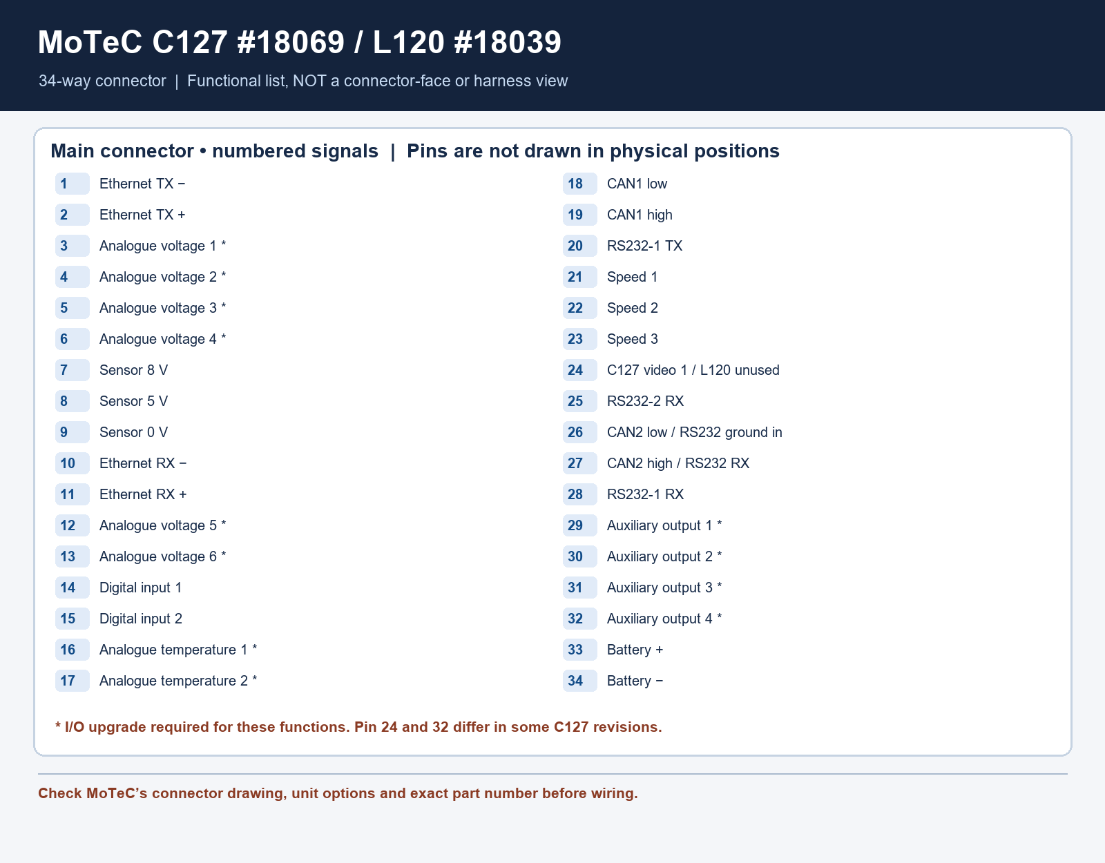
MoTeC identifies mating connector #65044 for both products. The cited C127 product page for part #18069 lists composite video on pin 24; the L120 #18039 page lists that pin as not used. The analogue and auxiliary functions marked “I/O upgrade” are optional. The table reflects the published names, including the dual-use CAN2/serial pins: check configuration and actual unit options. Sources: MoTeC C127 pinout and specifications; MoTeC L120 pinout and specifications. The C127 user manual supplies connector and wiring drawings. An older C127 #18036 datasheet describes pin 24 differently. The current C127 product table labels pin 32 auxiliary output 4, while a C127 manual also labels it LIN; confirm the exact part number, revision and enabled functions with MoTeC before using video or LIN.
| Pin | C127 | L120 |
|---|---|---|
| 1 | Ethernet transmit − | Same |
| 2 | Ethernet transmit + | Same |
| 3 | Analogue voltage 1 (I/O upgrade) | Same |
| 4 | Analogue voltage 2 (I/O upgrade) | Same |
| 5 | Analogue voltage 3 (I/O upgrade) | Same |
| 6 | Analogue voltage 4 (I/O upgrade) | Same |
| 7 | Sensor 8 V | Same |
| 8 | Sensor 5 V | Same |
| 9 | Sensor 0 V | Same |
| 10 | Ethernet receive − | Same |
| 11 | Ethernet receive + | Same |
| 12 | Analogue voltage 5 (I/O upgrade) | Same |
| 13 | Analogue voltage 6 (I/O upgrade) | Same |
| 14 | Digital input 1 | Same |
| 15 | Digital input 2 | Same |
| 16 | Analogue temperature 1 (I/O upgrade) | Same |
| 17 | Analogue temperature 2 (I/O upgrade) | Same |
| 18 | CAN1 low | Same |
| 19 | CAN1 high | Same |
| 20 | RS232-1 transmit | Same |
| 21 | Speed 1 | Same |
| 22 | Speed 2 | Same |
| 23 | Speed 3 | Same |
| 24 | Video input 1 | Not used |
| 25 | RS232-2 receive | Same |
| 26 | CAN2 low / RS232 ground input | Same |
| 27 | CAN2 high / RS232 receive | Same |
| 28 | RS232-1 receive | Same |
| 29 | Auxiliary output 1 (I/O upgrade) | Same |
| 30 | Auxiliary output 2 (I/O upgrade) | Same |
| 31 | Auxiliary output 3 (I/O upgrade) | Same |
| 32 | Auxiliary output 4 (I/O upgrade) | Same |
| 33 | Battery positive | Same |
| 34 | Battery negative | Same |
Wiring the system
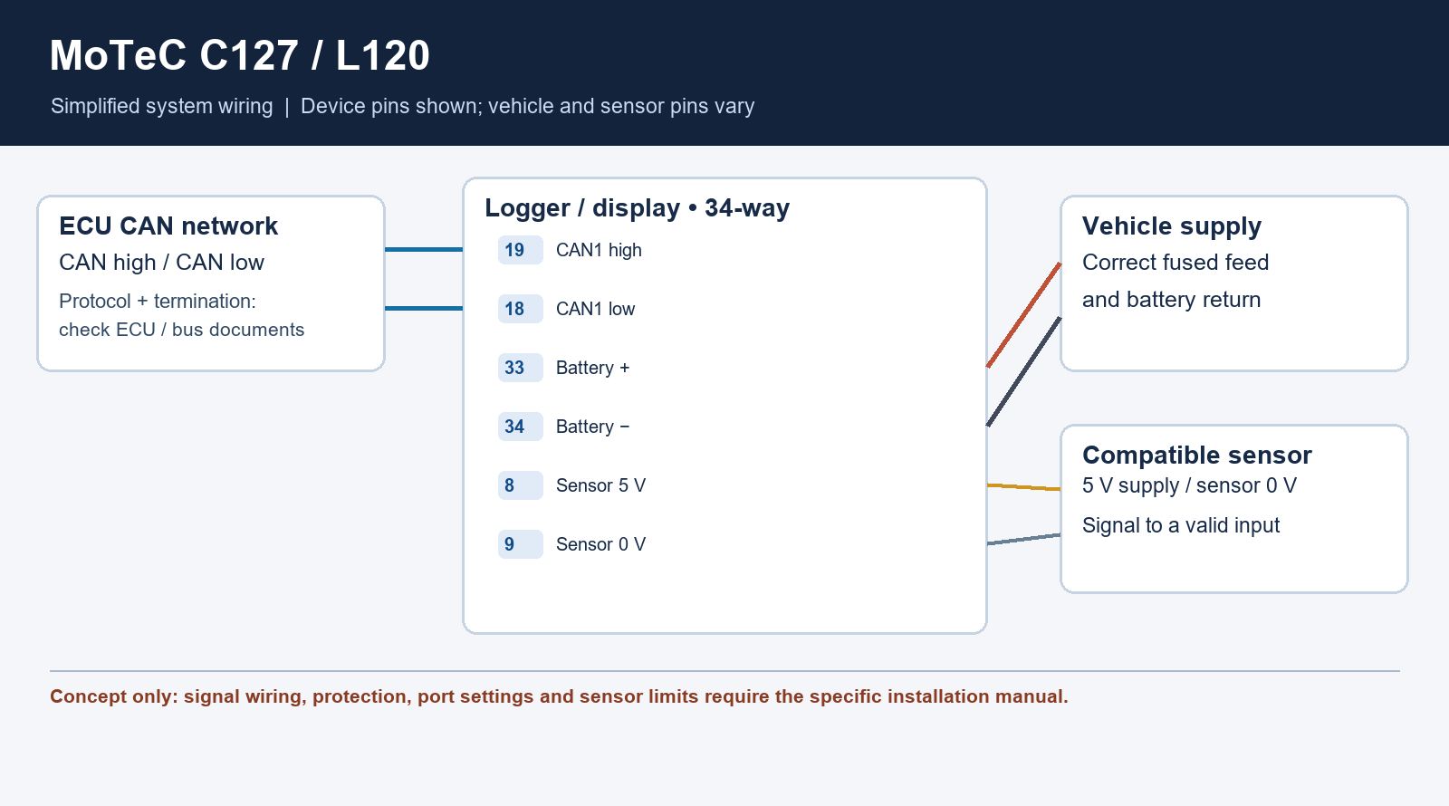
- Supply and sensors: pins 33 and 34 are battery positive and negative. Pins 7, 8 and 9 are sensor 8 V, sensor 5 V and sensor 0 V, respectively, not interchangeable battery or chassis connections. For C127 MoTeC specifies each 5 V and 8 V supply at 0.25 A maximum; verify sensor current, scaling and the input range in the relevant product documentation. Disconnect power before changing pins, seal unused cavities and use the correct contacts and tool.
- CAN and ECU data: CAN1 is 19 high/18 low and CAN2 is 27 high/26 low on the two named units. MoTeC recommends CAN for current MoTeC ECUs; M4/M48/M8 may require RS232 and an adaptor or PCI cable. Pin 27/26 can have serial functions, so verify port mode and baud rate before connecting. ECU-specific wiring and channel availability must be checked separately. The C127 manual specifies a twisted-pair CAN trunk with 100 Ω termination at each end, allowing a single terminator on a bus shorter than 2 m; check existing terminations before adding any, and follow the exact network’s documentation.
- C127 looms: MoTeC lists a terminated C12x race loom, #61259 input loom for upgraded analogue inputs, #61197 OBD-II-to-display loom, #61199 RS232 adaptor loom and optional USB-logging cables. Confirm hardware and vehicle support rather than assuming an OBD-II connector makes every ECU channel available. See C127 Race Logging Kit and loom options.
- Ethernet: the C127 and L120 product pages provide their network cable wiring and distinguish cable revisions A and B. Check the cable label and the correct revision table; do not identify a connection from wire colour alone. Ethernet TX and RX are described from each device’s perspective. MoTeC C127 Ethernet table.
- Telemetry: the T2 software/upgrade does not itself provide a physical radio or cellular connection. Choose the supported transmit and receive equipment, link, power and correct firmware for the unit. Do not equate a logger’s USB or Ethernet cable with a configured live telemetry system. See MoTeC T2.
Recording, analysis and telemetry
Choose channels for the question: engine speed, throttle, manifold pressure, lambda, temperatures and ECU limits for engine work; GPS speed, lap position, brake pressure and steering where fitted for driving analysis. Check sensor calibration, units, polarity and plausibility before comparing runs. Compare like operating conditions and remember that an ECU's calculated channel is not a direct measurement.
MoTeC i2 displays logs in graphs, gauges and reports and supports synchronised video. i2 Standard is available for MoTeC logger or ECU logs. i2 Pro adds advanced maths, multiple overlay laps and more components; MoTeC describes either a Pro Analysis upgrade on the recording device, which produces Pro files, or an applicable feature licence for other data formats. The licence and the log source matter; downloading software alone does not imply every file will have Pro features.
Logging records data for later download, whereas T2 telemetry sends information for monitoring while the vehicle is running. MoTeC lists T2 as an option on the cited logger families; telemetry also needs a suitable system and configuration. GPS lap timing requires the appropriate GPS equipment and setup. A display's live camera input is not by itself a video recorder.
Log-analysis software: MoTeC i2

i2 Standard analyses recorded data from MoTeC loggers and ECUs with logging enabled. It uses projects, workbooks and worksheets to organise graphs, gauges and reports; it can compare channels against time or distance, display track maps and use synchronised video where the recording is available. Use the appropriate device manager or M1 Tune to configure logging and retrieve the data before opening it in i2. MoTeC i2 features and compatibility; M1 log retrieval.
i2 Pro adds advanced maths, multiple lap overlays and unrestricted numbers of components, workbooks and worksheets. MoTeC describes two paths: an eligible logger or ECU's Pro Analysis upgrade records Pro-compatible files, or a suitable PC feature licence enables particular file types in i2 Pro. For example, the licence to open MoTeC Standard log files in i2 Pro is PC-specific; confirm the exact device, logging upgrade and licence before purchasing. i2 Standard is included with a logging upgrade on the cited C127; package and product entitlements vary. i2 comparison and licence details; C127 manual.
Practical workflow: retrieve a logged session, open it in i2 and compare speed, RPM and other recorded channels by time or distance; add GPS position, lap comparison and video where fitted. MoTeC documents export including CSV and MATLAB formats. Its software is available from the official downloads library; consult MoTeC i2 training for overlays, lap beacons and video synchronisation.
Step-by-step: retrieve and analyse a MoTeC log
This example covers a C127 display logger and MoTeC i2. Other devices can use a different connection and retrieval program; check the exact model, enabled logging upgrade and instructions before starting.
- Install the tools: obtain i2 and the appropriate Dash Manager or device manager from the MoTeC downloads library. Check that logging is enabled on the individual logger and that the chosen i2 edition can open its file.
- Connect and retrieve: after the session, connect the powered C127 to the PC using its documented connection. In its Display Logger Manager, select Online → Get Logged Data, and wait for the transfer to the computer to finish. MoTeC says the user may choose whether to clear logger memory after unloading; keep the recording until the downloaded file has been checked. C127 manual, retrieving logged data.
- For an M1 ECU instead: in M1 Tune use Online → Retrieve Logged Data, choose the relevant logging system and destination, and select the option to retrieve and keep the data. Enter the requested details and choose to convert the retrieved image to an i2 log file. This M1 procedure is not the C127 menu. M1 Tune retrieval guide.
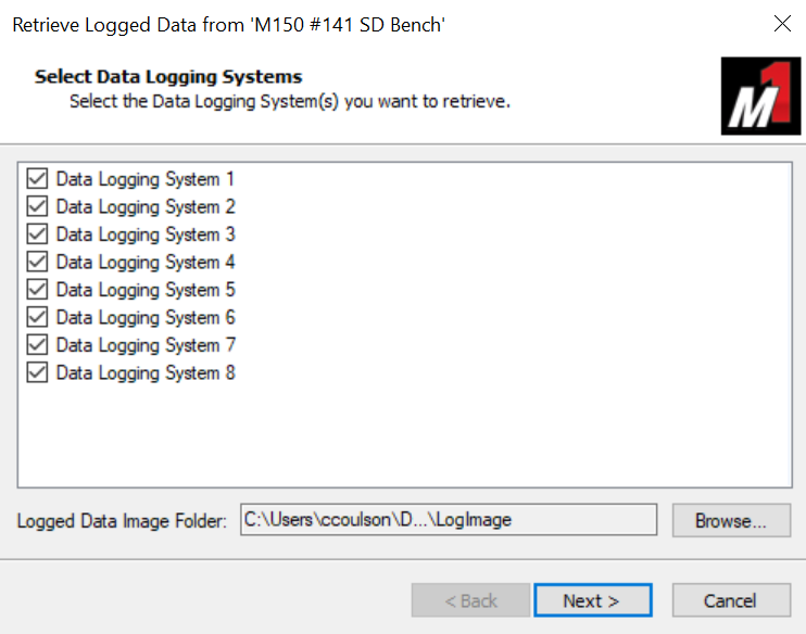
M1 Tune 1.5: choose the logging systems and image destination. This is the M1 ECU workflow, not the C127 Dash Manager screen. Image: MoTeC, reproduced with permission; manufacturer guide. 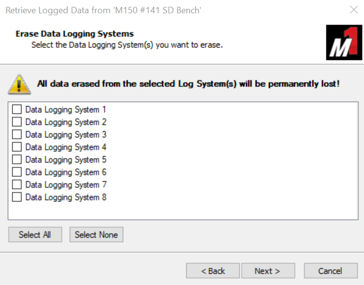
M1 Tune 1.5 erase-selection dialog: no logging system is selected for erasure in this example. Read the choices carefully to retain the original data. Image: MoTeC, reproduced with permission; manufacturer guide. - Open the run: start i2 and open an appropriate project such as a Circuit project. Select the downloaded log file; in i2, File → Open Log File provides access to the log list. Keep the actual .ld data file with its associated details file when sharing a run. MoTeC example of selecting and sharing an i2 log.
- Inspect data: display a graph worksheet and add recorded channels such as speed, RPM or throttle; check units and plausible values. Review against time for an engine event or distance for a track comparison. Position and lap analysis require the appropriate recorded position and lap markers.
- Compare laps: choose a reference lap and overlay another recorded lap or session to compare braking points, throttle application and speed. Use the track, time and channel reports where supported. Overlay count and advanced reports depend on the i2 edition and licence.
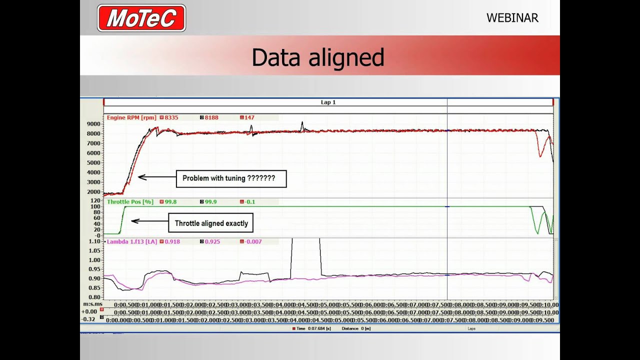
MoTeC training example of aligned RPM, throttle and lambda traces; this is a webinar slide illustrating the comparison, not an i2 menu screenshot. Image: MoTeC, reproduced with permission; manufacturer training. - Add video if recorded: link the matching video and data in i2. The synchronisation method depends on the camera system, logger and software edition; some combinations synchronise automatically, while other setups require separate hardware or manual alignment. See MoTeC i2 features, video support and licensing and its training resources.
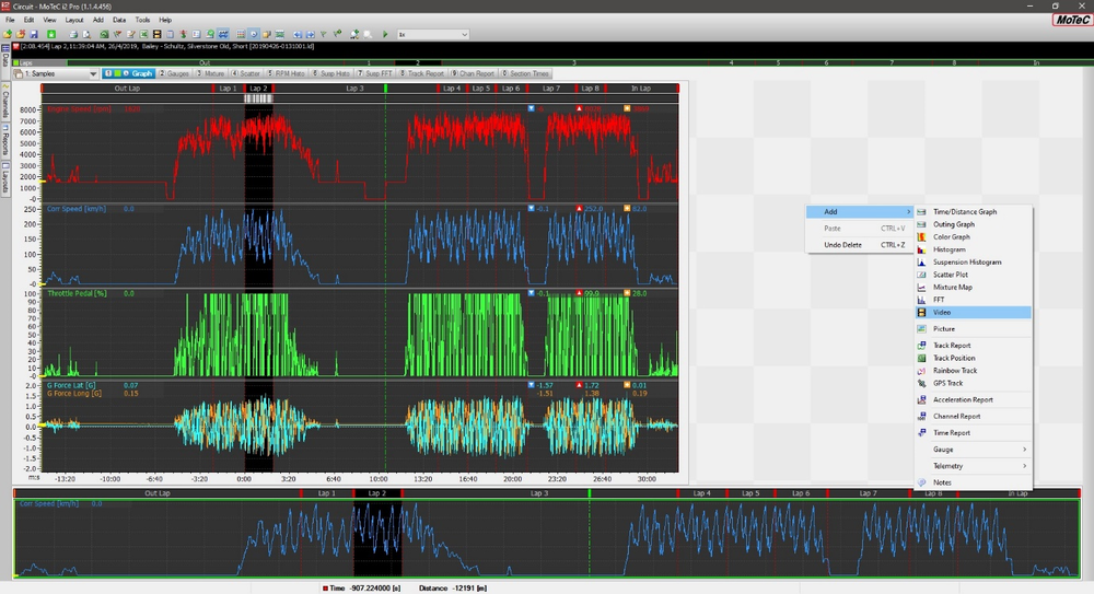
MoTeC i2 Pro example: logged channel traces and the menu for adding a video panel. This screenshot shows RACELOGIC's VBOX HD2 integration workflow; methods vary by camera system. Image: RACELOGIC, reproduced with permission; manufacturer guide.
i2 Standard and Pro have different capabilities. A device-level Pro Analysis upgrade and an i2 Pro feature licence are different entitlements; verify the model and file before relying on Pro functions.
Sources and product photographs
- MoTeC display logger comparison and kit contents.
- MoTeC C125 product page, C127, C1212 and C187; product photographs, logging and upgrades.
- C125 Race Logging Kit, MoTeC; kit contents and USB logging prerequisite.
- MoTeC data logger comparison, L120, L120 USB and L180; product photographs, logging, I/O and compatibility.
- MoTeC i2 analysis and T2 telemetry.