Fuel trims show how much an engine control unit (ECU) is correcting its calculated fuel delivery in response to exhaust oxygen feedback. They are useful diagnostic clues even when no fault code is stored. This guide focuses on closed-loop petrol engines; diesel, lean-burn and some direct-injection strategies use different controls and displays.
How the feedback loop works
The ECU calculates a base fuel quantity from measured or estimated air and operating conditions. When the system enters closed loop, it compares exhaust sensor feedback with the commanded mixture and adjusts fuelling. For conventional petrol at stoichiometry, lambda is 1; the familiar approximately 14.7:1 air-to-fuel ratio is an approximation and changes with fuel composition. Other operating conditions may call for a different mixture.
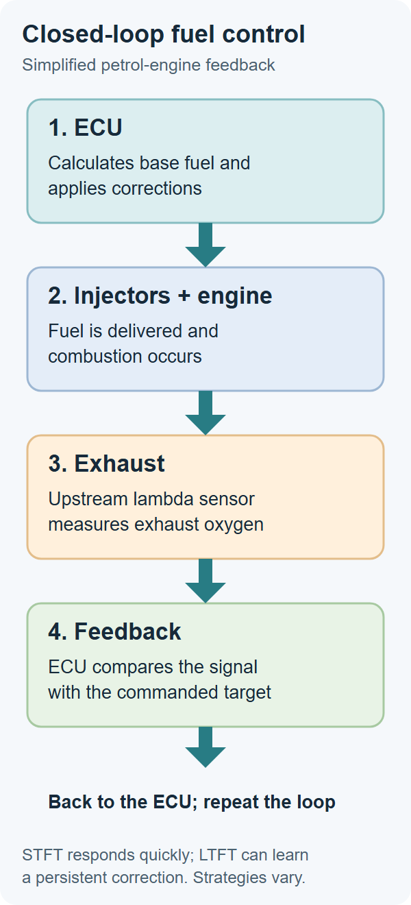
Original illustration created for Tuning Wiki.
| 1. Calculate | 2. Deliver | 3. Measure | 4. Correct |
|---|---|---|---|
| Air, speed, temperature and load → base fuel | Injectors deliver fuel → combustion | Upstream lambda sensor measures exhaust oxygen | ECU compares feedback with target → adjusts fuel and repeats |
Diagram: simplified closed-loop fuel control. The exact inputs and control strategy depend on the vehicle. US EPA: fuel system trim and feedback.
Short-term and long-term trim
- Short-term fuel trim (STFT) is the faster feedback correction. It changes as the ECU responds to the sensor and operating conditions.
- Long-term fuel trim (LTFT) is a learned correction that can take over a persistent adjustment, leaving STFT room to respond. Some ECUs learn separate corrections for idle, part load and other operating regions.
| Display | What the ECU is doing | What it suggests |
|---|---|---|
| Positive percentage | Adding fuel relative to its base calculation | Feedback indicates a lean tendency, or feedback is misleading |
| Negative percentage | Removing fuel relative to its base calculation | Feedback indicates a rich tendency, or feedback is misleading |
| Near zero | Little indicated correction for that value at that moment | Check loop status and both trims; a zero or inactive STFT does not prove the system is healthy |
Read fuel-system status alongside the trims. During open-loop operation, such as some cold-start, fault or high-load conditions, the displayed STFT may be inactive, fixed or otherwise not a live closed-loop correction. Some ECUs still apply learned corrections in open loop; behaviour varies. A recently reset LTFT near zero also does not establish that the underlying fault is fixed.
Some manufacturer-specific data uses a multiplier or a different name instead of a percentage: for example, 1.00 may mean no correction. Do not confuse that correction factor with lambda 1.00. Check the data definition for the vehicle. Manufacturer explanation of fuel corrections and learning.
On systems where the manufacturer specifies it, STFT and LTFT for the same bank can be added as a useful approximate indication of total correction. For example, +12% LTFT and −3% STFT suggest approximately +9% overall. It is a diagnostic approximation, not a universal formula for exact injector pulse width. A small STFT alone can hide a large learned LTFT. Compare with the manufacturer's method, limits and conditions.
Give each steady operating point time to settle and record STFT and LTFT together. An LTFT change between idle and part load may reflect a switch to another learned cell rather than an immediate change in the fault. Keep the vehicle, bank, temperature, loop status and PID definition consistent when comparing readings. Manufacturer explanation of idle and part-load adaptations.
Reading the pattern

Original illustration created for Tuning Wiki. The points are examples, not diagnostic limits; several faults can produce similar patterns.
| Observed pattern | Possible direction for testing |
|---|---|
| Positive at warm idle, closer to zero at a steady raised speed | Investigate an intake or crankcase ventilation leak; airflow measurement and other faults can produce similar results. |
| Positive at idle and under load, or increasingly positive under load | Check fuel delivery and pressure under the specified conditions, air measurement, injectors and exhaust leaks. A stationary raised-speed test is not a substitute for a load test. |
| Negative in several operating regions | Investigate excess fuel, purge flow, fuel pressure, injector leakage or a biased sensor/input, according to the vehicle's test plan. |
| One bank differs from the other | Compare bank-specific intake and exhaust leaks, injectors and sensor circuits. A shared fault can still affect banks differently. |
| Large corrections but no code | Record the evidence and investigate; a fault may not have met its monitor conditions or threshold. |
These are hypotheses, not component verdicts. For example, a fixed air leak often has a greater proportionate effect at idle, but different airflow models and faults can change the pattern. A GM service procedure for specific vehicles compares idle and approximately 2,000 rpm and lists several possible causes when trim improves; it does not establish a universal limit. GM service information.
Worked example: positive trim at idle
Illustrative example: a warm, single-bank petrol engine with a mass-airflow sensor idles roughly. The scan tool reports closed-loop control, and the technician has recorded the fault codes and freeze-frame data without resetting adaptations. The figures below are invented to show the reasoning; they are not universal pass limits. For this example, the vehicle procedure permits STFT and LTFT from the same bank to be added as an approximate diagnostic correction.
- Warm idle, bank 1: LTFT +12%, STFT approximately +10%; combined indication approximately +22%.
- Steady 2,000 rpm in Park, bank 1: LTFT +3%, STFT approximately +2%; combined indication approximately +5%.
Interpretation: at idle the ECU is adding substantial fuel in response to its feedback. At raised speed the indicated correction is smaller. This pattern makes an intake or crankcase-ventilation air leak a reasonable test direction, because a leak can be a larger proportion of the total airflow at idle. It does not prove a leak: airflow measurement, a change of learned cell or other faults can also affect the comparison. The readings are taken at stable conditions with the engine still in closed loop; a raised-speed test in Park does not test fuel delivery under road load. GM service information: idle and raised-speed comparison on specified vehicles.
Test and repair: following the vehicle and smoke-machine procedures, the technician finds smoke escaping from a split intake vacuum hose downstream of the airflow sensor. The hose is replaced and a repeat leak test shows no smoke at the repair. The smoke test confirms a leak at that location; the fuel-trim pattern alone did not identify the hose.
Verify: after the appropriate relearn and with closed loop confirmed, the same bank is checked at the same operating points. In this example idle now reads LTFT +2% and STFT approximately +1%; at 2,000 rpm it reads LTFT +1% and STFT approximately +2%. The rough idle has gone and the fault does not return on a suitable test drive. These results support the repair; compare actual readings and readiness with the vehicle procedure, and do not treat an immediately reset LTFT as proof of success.
Worked example: negative fuel trim
Illustrative example: a single-bank petrol engine runs in closed loop at normal temperature and has a stored P0172. The technician records the codes, freeze-frame data and trims before clearing or resetting anything. The following values and test results are invented to demonstrate the method; they are not universal diagnostic limits. This example assumes the vehicle's procedure allows the two trims for the same bank to be added for an approximate combined indication.
- Warm idle, bank 1: LTFT −16%, STFT approximately −5%; combined indication approximately −21%.
- Steady 2,000 rpm in Park, bank 1: LTFT −12%, STFT approximately −3%; combined indication approximately −15%.
Interpretation: the ECU is removing fuel in both conditions in response to its feedback. This suggests a rich tendency, but the numbers alone do not prove that the fuel injectors or lambda sensor are faulty. Excess fuel vapour, high fuel pressure, injector leakage, inaccurate airflow or temperature inputs, and misleading sensor feedback are among the possibilities. Learned values can differ between operating cells, and the stationary raised-speed test does not establish what happens under load.
Narrowing it down: in this example, the technician checks the relevant service information, fuel specification, sensor data and fuel delivery using the manufacturer's procedures. No fault is found in those checks. The oil level is above its expected range and the oil smells strongly of fuel; the vehicle has repeatedly been driven on very short trips. Further investigation confirms fuel-diluted oil and finds no fuel-system fault responsible. Fuel vapour from the crankcase can contribute to a rich condition through the ventilation system. Fuel smell or oil level alone does not establish the cause: investigate and repair any fuel leak or other underlying fault. A GM bulletin describes fuel-diluted oil associated with short trips and negative LTFT on specified vehicles; its procedure and limits are vehicle-specific.
Repair and verify: in this example the confirmed contaminated oil and filter are replaced using the vehicle procedure. The technician clears the code as directed, allows the ECU to relearn, then repeats the warm closed-loop checks at the same operating points. Idle now shows LTFT −2% and STFT approximately −1%; at 2,000 rpm LTFT is −1% and STFT approximately −2%. Following an appropriate test drive, the code has not returned. Compare readings and monitor status with the vehicle's procedure: a zero LTFT immediately after a reset is not proof of repair, and a test drive alone may not complete every monitor.
Common fault codes
P0171 and P0172 generally identify a lean and a rich fuel-system condition on bank 1; P0174 and P0175 identify lean and rich conditions on bank 2 respectively. The code indicates the monitor result, not the failed component. Confirm the exact description and diagnostic procedure for the vehicle, including its bank identification. Monitor thresholds and enabling conditions vary. Toyota: fuel-trim code examples.
Workshop procedure
- Record the complaint, fuel type, modifications, stored and pending codes, freeze-frame data and readiness. Inspect intake ducting, hoses, PCV connections, wiring and exhaust for obvious faults. Do not clear codes or adaptations before recording the evidence.
- Bring the engine to the relevant temperature and verify fuel-control status. Log STFT and LTFT for each available bank, engine speed, load, coolant temperature, airflow or manifold pressure, commanded lambda and upstream sensor data where supported.
- Record a stable idle, then a stable raised speed in a safe stationary position, following the vehicle procedure. Compare the same bank and operating conditions. If the concern occurs under load, capture a suitable road or dynamometer log safely with a second person operating the scan tool.
- Use the pattern to select a test: a regulated smoke test for an intake leak, fuel pressure and delivery tests under the specified conditions, injector tests, or checks of airflow and sensor wiring. Follow vehicle and equipment procedures for pressure and test medium; do not apply unregulated shop air to the crankcase or fuel system. For fuel-vapour systems, use the specified inert gas and leak-test equipment. Petrol direct-injection systems can retain high pressure: follow the manufacturer’s depressurisation and connection procedure before opening a fuel circuit. Bosch: leak testing and inert gas.
- If sensor feedback and other evidence disagree, compare with an exhaust gas analyser and test the sensor and circuit using the correct procedure. Scan-tool values are processed and may be limited or filtered; a suitable oscilloscope can reveal a signal the displayed data does not show. Check the circuit, reference and heater as applicable before replacing parts.
- Repair the confirmed cause, then follow the manufacturer's instructions for clearing faults or resetting adaptations if appropriate. Recheck for leaks, repeat the original operating conditions and allow the ECU to relearn before judging the final result.
When feedback tells the wrong story
A positive trim means the ECU is adding fuel; it does not independently prove that the actual exhaust mixture is lean. An exhaust leak upstream of the sensor, misfire, wiring fault or a faulty sensor can distort the oxygen signal. If a gas analyser indicates a rich exhaust while the ECU is adding fuel, investigate the feedback and its circuit as well as the fuelling system. A newly fitted sensor or other part still needs to be tested. Bosch recommends comparing sensor data with exhaust-gas readings and, where necessary, checking the signal with an oscilloscope. Bosch: lambda and air-mass sensor diagnosis.
A conventional narrowband zirconia sensor and a wideband air–fuel sensor have different signals and test methods. Do not apply a 0–1 V switching test to every sensor; use the manufacturer's pinout, equipment and procedure. Exhaust oxygen can also be affected by misfire, so interpret the signal alongside combustion and gas-analysis evidence. Bosch: lambda sensor signal types.