A rolling road, or roller chassis dynamometer, tests a complete vehicle with its driven tyres turning rollers while the vehicle is restrained. The measurement boundary is at the roller and tyre contact: gearbox, differential, bearings and tyres lie between the engine and the measuring system. It is useful for before-and-after tuning, fault finding under load, emissions and drive-cycle testing.
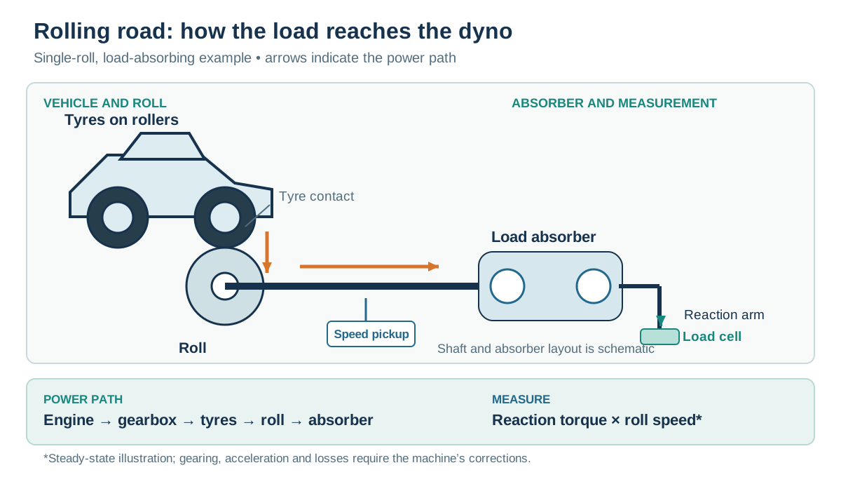
How a roller system works
The tyre turns a single large roller or a pair of smaller rollers. The rolls have known rotational inertia and may be connected to one or more power absorbing units. In a load-bearing design the rotating roll drives the absorber, while its housing is mounted so its reaction acts through a torque arm onto a load cell. A speed sensor measures roller rotation. At a steady point, power transferred through that measurement boundary is torque multiplied by angular speed; during acceleration, power also goes into accelerating the rolls and other rotating parts. The controller must account for the relevant inertia and losses. Mustang MD-600 operation manual.
Pure inertia machines calculate output from the acceleration of a calibrated mass. A braked machine can also impose controlled resistance: for example an eddy-current absorber turns vehicle power into heat and its excitation regulates load. A motor-capable electric machine can additionally drive the rollers where its design allows. These are capabilities of specific machines, not properties of every rolling road.
Testing and road simulation
In a sweep, the vehicle accelerates the rolls over an RPM range. A load-holding dyno can instead maintain a chosen speed while throttle or load is varied, useful for steady-state mapping and diagnosis. Road-load simulation can approximate rolling resistance, aerodynamic drag and gradient as functions of speed, with mechanical or electronically simulated inertia where fitted. Simulation depends on the chosen vehicle data, calibration and the control system's response; stationary testing does not reproduce every road airflow or transient. SAE 930392: chassis dynamometer performance tests.
Two-wheel and all-wheel drive
The equipment must suit driven axles, wheelbase, track, axle weight, speed and torque. Some all-wheel-drive vehicles require synchronised front and rear rolls or special procedures; permanent, automatically coupled and electrically driven axles can behave differently. Follow the vehicle and dyno maker's instructions; do not assume that a 4WD mode or disconnected axle is permissible.
Setup and interpreting a printout
Inspect tyre condition and pressure, secure the vehicle using approved restraint points, align it on the rollers, provide cooling airflow and exhaust extraction, and verify emergency stop and speed limits. Control tyre pressure, tie-down method, gear, warm-up and temperatures across comparisons. Tyre deformation, rolling resistance and slip, dyno and bearing losses, and roller geometry influence output and repeatability; twin-roller losses have been studied explicitly in SAE 2017-36-0212.
Report whether power is measured at the wheels/rollers or estimated at the engine, along with correction standard, gear, RPM source and conditions. A coastdown-based drivetrain-loss estimate is model-dependent; adding it to wheel power does not make a direct crankshaft measurement. Compare runs on the same calibrated equipment with consistent settings rather than treating different dyno figures as interchangeable.
Roller layouts and mechanical loading
Single large drum: the driven tyre contacts one main roller. The drum can provide the calibrated rotating inertia and may be coupled to a brake through a shaft or drive. Installation can be above ground or in a pit, depending on the model. Roller width and track range determine where the tyre can safely sit. Dynojet's 224/424 installation guide illustrates large-drum chassis layouts, pit dimensions and eddy-brake options.
Twin rollers: each driven wheel rests between two smaller rollers. An engineered linkage can couple the rollers or transfer power to an absorber; the arrangement is machine-specific. Tyre deformation and contact geometry differ from a large-drum system. The historical Mustang MD-AWD-500 manual specifies a twin-roll layout, with one or two optional eddy-current absorbers according to version.
On any roller dyno, the brake mechanism and measurement strategy are separate choices. A speed pickup records roll speed; a braked machine may measure absorber reaction with a load cell, whereas an inertia machine calculates net torque from the known rotating inertia and acceleration. A combined system must account for inertia during a sweep. The reported number can also depend on friction, tyre deformation, filtering and the controller's correction method. See inertia dynamometers and measurement and interpreting results.
AWD axle control and tyre contact
A four-wheel-drive rolling road needs a suitable roller set for each driven axle and a wheelbase adjustment that fits the vehicle. Some designs mechanically link front and rear roller systems; others use independent brakes, sensors and electronic control. A mechanical link is an arrangement for a specific machine and does not by itself prove compatibility with every drivetrain. The Mustang MD-AWD-500-XL specification documents a linked roller example; Dynojet describes a mechanical-link option for specified models.
Wheel speed, tyre rolling radius and restraint affect contact. Different tyre sizes, pressures and roller speeds can interact with centre differentials, electronically controlled clutches, traction control or electric axles. Follow the vehicle and dyno manufacturers' permitted test configuration; do not disable or disconnect a drive system solely on the basis of a generic procedure. Ensure sufficient traction and safe restraint within the machine's rated axle weight, speed and power envelope.
Test modes and comparison
- Inertia sweep: net accelerating torque is inferred from the roller's known inertia and change in speed, with the system's applicable corrections. Sweep rate is the result of available torque and inertia rather than an independently commanded load.
- Loaded sweep: a controlled absorber resists the vehicle as speed rises. Depending on the controller, the operator may request a rate or profile; measured load and acceleration-related inertia both matter.
- Steady speed or load: a controller adjusts braking within its available envelope while the vehicle's throttle or power demand is changed. This permits repeatable mapping at supported points and diagnostic checks under load.
- Road-load or drive-cycle simulation: a configured controller uses a vehicle/load model to command resistance. A passive brake cannot provide active downhill or overrun motoring; that requires a suitably equipped electric machine. See control systems.
Roller or wheel speed must be associated with a reliable engine-speed signal or a correctly established gear ratio before plotting results against engine RPM. A coastdown measurement may support a supplier's estimate of losses, but it is not a direct measurement of every drivetrain loss under power. Record test mode, gear, tyre condition and pressures, warm-up, correction standard and actual reported measurement boundary. Repeated tests in comparable conditions are more meaningful than treating a single peak as a universal conversion between different dynamometers.
Rolling-road makes and models
The following examples illustrate different vehicle and absorber configurations; the cited specifications apply to the named versions. Check current availability, restraint method and continuous torque–speed and cooling limits with the supplier.
| Manufacturer and model | Layout and operating principle |
|---|---|
| Dynojet 224x / 224xLC | 2WD large-drum chassis machines; Dynojet describes the 224xLC with an eddy-current load option for additional controlled tests. Manufacturer range. |
| Dynojet 424xLC2 / Linx | 4WD chassis machine with documented eddy-current equipment; the manufacturer describes a mechanical roller-link option for specified dynos. Model documents. |
| Mustang Dynamometer MD-AWD-500-XL | AWD roller system with linked axles, air-cooled eddy-current absorber and digital load control; options and ratings vary. Manufacturer specification. |
| Dyno Dynamics Dynotech Series II 4WD | 4WD rolling road with synchronised axle control and CAN-based electronics; the manufacturer lists different retarder configurations. Model page. |
| COSBER Dynocosber 1000P / 2000P | Manufacturer examples of 2WD and 4WD roller systems respectively, listed with eddy-current retarders in its comparison. COSBER model comparison. |
| Dyna Pro S125-LC | Motorcycle rolling road with eddy-current load control; the S125 inertia model and LC version are distinct configurations. S125-LC details. |
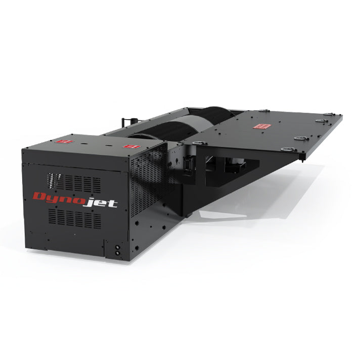
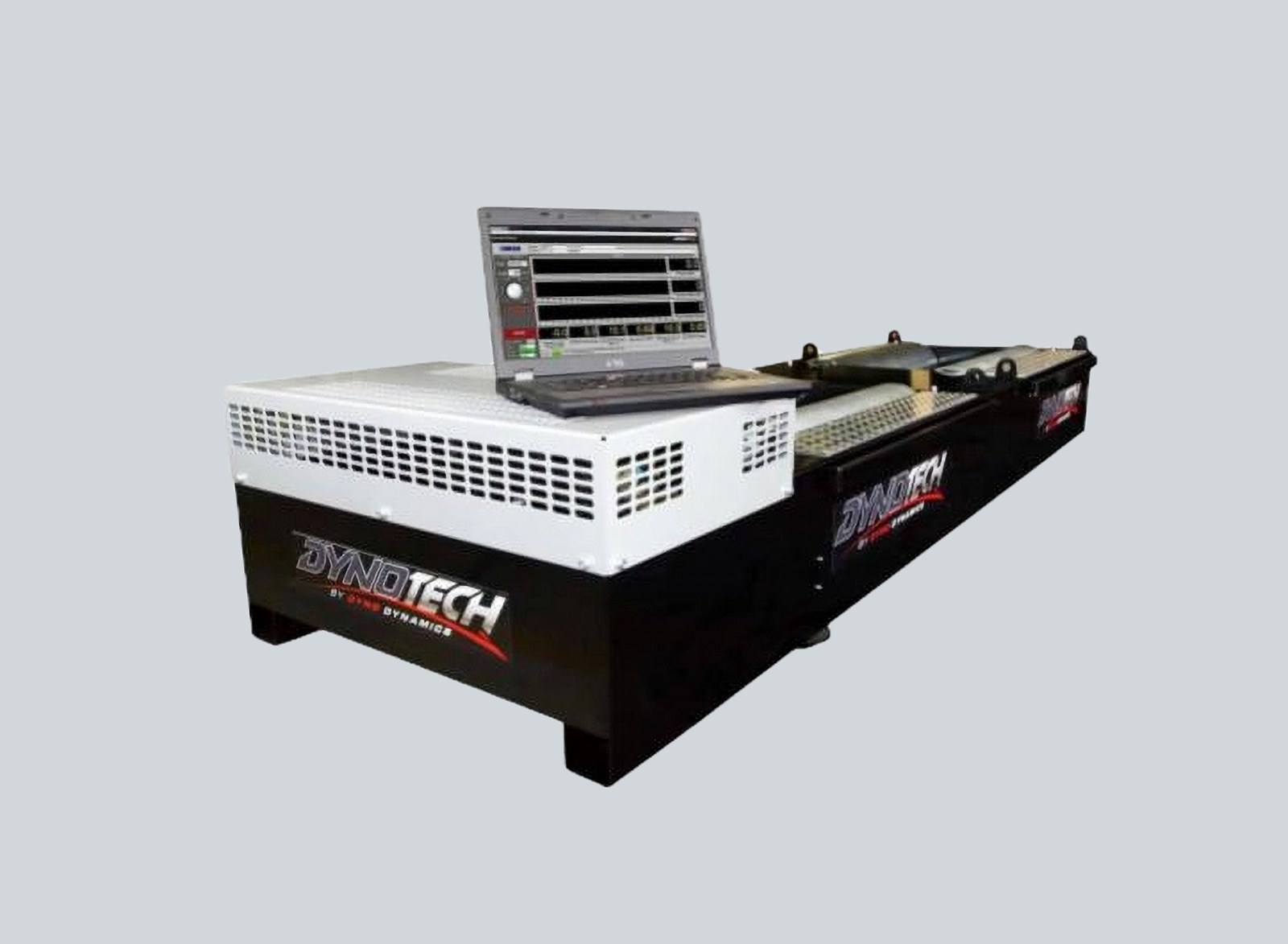
Manufacturer example
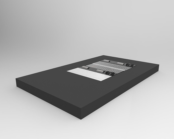
Advanced Dyno Solutions describes a 500 mm single-roll eddy-current chassis system in 2WD and 4WD configurations, including a synchronised-roll option for compatible vehicles. Configuration and capacity depend on the system supplied; consult the manufacturer’s chassis-dyno page.
See also: Dynamometers overview · Rolling roads · Engine dynamometers · Hub dynamometers · On-car and portable systems · Inertia dynamometers.
Related company profiles
COSBER / DynoCosber manufactures roller dynos with integrated controls.
Advanced Dyno Solutions · Dyno Developments · Dyno Dynamics · Dynojet · Mustang Dynamometer · Dyna Pro.