An original-equipment dynamometer control system is the measurement, load-control and operating equipment supplied or specified by a dyno manufacturer. It may comprise several separate items: a real-time controller, speed and torque inputs, brake power electronics or hydraulic-valve drivers, a pendant or console, PC software and optional sensor modules. Names and capabilities are specific to a machine, generation and installed options.
Factory equipment can often be repaired, updated or replaced through a manufacturer-supported conversion. This guide documents selected systems, including older and current examples; it is not a claim that every model or revision supports every feature. For general operating principles and aftermarket alternatives, see Dynamometer control systems.

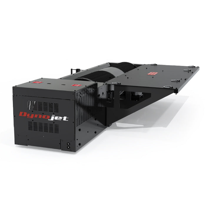
Dynojet: DynoWare RT and Power Core
Dynojet uses DynoWare RT electronics and the Power Core software suite, which includes WinPEP 8 Dyno Control and Data Center. Dyno Control provides live gauges, test recording and load-control functions when supported; the electronic module stores the dyno configuration. Dynojet's software glossary distinguishes the computer application from the dyno electronics and describes PID coefficients for supported brake controls.
- Hardware: the DynoWare RT specification lists Ethernet, two inductive and two optional optical engine-RPM pickup connections, four 0–5 V analogue inputs, four proprietary DJ-CAN expansion ports, atmospheric sensor connections and a pendant. Individual accessories and sensors may be optional.
- Brake and channels: the Vector-X4000 hub-dyno installation guide identifies two eddy-current brake drivers and two speed pickups, with load-cell calibration performed in Power Core. This describes that two-hub installation, not every Dynojet configuration.
- Manufacturer upgrades: a 200i/250i DynoWare RT upgrade guide documents a main module and speed pickup, with optional AFR and eddy-brake driver modules. Check the exact original model, brake, harness and upgrade kit; the existence of one conversion does not establish universal fitment.
Dynojet's RPM setup guide describes alternative RPM sources, including a configured drum-speed ratio and software-defined source. Engine-RPM accuracy depends on choosing and configuring the appropriate source.
Dyno Dynamics and Dynotech: Series I and Series II
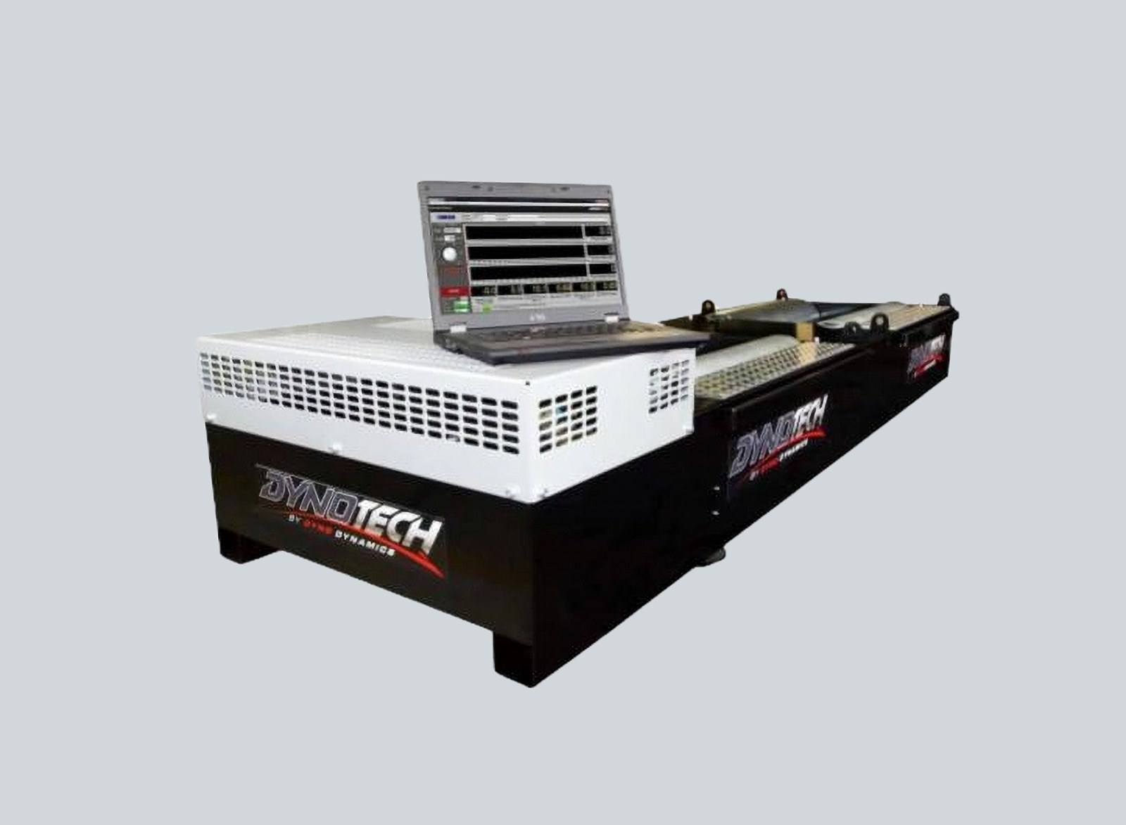
Dyno Dynamics has offered several generations of chassis and hub-dyno controls. The Series II upgrade is described by the maker for Series I chassis dynos and compatible older HUB2000 systems. It replaces the earlier Comms Hub/PDA arrangement with a Series II interface box, updated firmware and Windows software, operated using a wireless keyboard. The manufacturer lists support for modern CAN modules, OBDII and AFR interfaces and customer/run-data migration; options, existing pit equipment and PC compatibility should be confirmed per installation.
The newer Series II HUB2000 lists CAN-based controls, automatic weather measurement, ECU/OBD integration and graphing; those specifications must not be projected backwards onto every Series I machine. The supplier also advertises an Analog-to-Windows upgrade separately, so identify the original system before specifying parts.
A remote handset alone is not a complete brake-controller replacement. For example, Torque Up's refurbished MC75 handheld kit is described for dynos originally using Bluetooth PDA control and tested on software versions 7.2–7.5; its supplier says it does not replace older wired controllers and lists W2A as untested. This is an independent supplier's compatibility statement, not a Dyno Dynamics factory specification.
Mainline DynoLog: CAN Control System
Mainline DynoLog's CCS means CAN Control System. On the ProHub AWD CCS, a central display/control unit communicates with remote control modules over a CAN network, while the Windows application provides test setup, displays and logging. The maker describes mapped eddy-current retarders with feed-forward plus PID control.
- Documented test modes on the ProHub AWD CCS include fixed-speed and fixed-torque operation, road-load simulation, linear and non-linear ramp tests, drag simulations and left/right torque balancing.
- The published configuration includes axle-speed sensors and load cells; the software supports configurable CAN data and logged or plotted channels. Brake count and channel layout depend on the model.
- The portable ProHub listing describes a weather station, engine-speed inputs and twin-channel lambda in its stated package, with options such as CAN thermocouples, an EX7 input expander and VFD fan control. Verify package content and subscription terms at quotation.
Mainline publishes model-specific wiring, CAN setup and software information in its downloads library. Do not assume CCS documentation applies unchanged to older DynoLog generations.
Dynolyze: independent hub controller
Dynolyze describes a stand-alone hub controller which can perform basic dyno operations without a PC; the PC software handles analysis and additional functions. The manufacturer's control-system page lists 2 or 4 hub speed inputs, load-cell inputs, brake-temperature inputs and individual brake PID calculations, according to the installed configuration.
- The listed system provides four 0–5 V sensor inputs, a PC CAN connection, automatic weather sensing and a 0–10 V fan-control output.
- The maker describes an IGBT brake power supply with a 1,200 Hz current-control loop/PWM and temperature-dependent duty limits. These are manufacturer specifications for this system, not generic settings to copy to another brake.
- PRO software options described by Dynolyze include selected CAN integration, knock-monitor data and differential-lock testing. Confirm licences, devices and control channels with the supplier.
Dynapack: axle and individual-hub control
Dynapack hydraulic pods use a controller and sensors with the hub-driven pump arrangement. Its EV information describes newer hardware with two closed-loop control units per axle and software-selectable independent hub or axle-control modes. The maker says that hardware is compatible with existing pods and pod cables, but the actual generation, feature licence and vehicle combination still need confirmation. Earlier axle control should not be assumed to have independent per-hub loops.
Rotronics: Dynascan for Hubscan
Rotronics' Hubscan product page describes the classic eddy-current Hubscan with Dynascan Essential and Hubscan Plus with Dynascan Advanced and an IMP-A acquisition module for ambient conditions, lambda and available OBD data. The Hubscan brochure describes graphs, data tables, statistics and optional video. The separate Hubscan AC development system has its own four-quadrant machine and control configuration; do not assume that an eddy-current Dynascan package controls every AC installation.
ROTOTEST: Energy HDC, DynoVision and Datmon
ROTOTEST Energy uses electric four-quadrant hub machines. The manufacturer identifies a system control cabinet, a main power unit containing drives and converters, and a real-time controller. DynoVision operates the equipment; Datmon handles measurement and reporting. The system description specifies front-end torque transducers and speed sensors; the Energy 4WD datasheet identifies its HDC high-dynamic controller and constant-speed and road-load modules.
Software, inverter/drive and electrical machines are separate components. Motoring and grid recovery depend on the complete Energy configuration; the older VPA-RX family used hydraulic absorbers and should not be treated as electrically identical.
SuperFlow: WinDyn and WinDyn5
SuperFlow's SF-902S manual separates the power absorber from its data acquisition and control system: sensors, central processing, operator interface and a load actuator work with WinDyn PC software. The WinDyn5 product page describes configurable testing and analysis for supported systems; channel count, acquisition rate and options depend on installed equipment.
WinDyn5 conversions are advertised for specific SuperFlow SF-901, SF-902, SF-3000BW, SF-849, SF-832, SF-880E and SF-250A machines, and for certain other manufacturers' engine or chassis dynos. Treat this as a supplier's conversion service: confirm the actual dyno, sensors, absorber driver and included work before assuming compatibility. The earlier WinDyn users' guide identifies 1942/2620- and 2242-based acquisition hardware and notes some upgrades require a software update.
Froude: Texcel V4 and InCell
Froude supplies controllers for engine and industrial test cells. Its Texcel V4 family includes V4-H for hydraulic dynos, V4-HE for hydraulic dyno and engine control, V4-EC for eddy-current dynos and V4-ECE for eddy-current dyno and engine control. The engine variants include throttle-actuator control; hydraulic versions can be configured for different valve types. The controller, power module, interlocks and actuator must match the absorber.
InCell uses a Qube or rackmount base controller, embedded real-time control, expandable I/O and PC automation software; an optional desktop panel provides manual demand controls. The supplier lists CANopen and EtherCAT compatibility for this system. These are test-cell controllers, not automatically drop-in replacements for a vehicle workshop hub dyno.
Dynocom: model-specific control packages
Dynocom has supplied different controller and software generations. Its Dyno X brochure lists a controller, software, two differential analogue inputs, a DC-JBox and an atmospheric module with that package; verify which components, channels and brake drivers are actually fitted before ordering replacement parts. The AWD 2000 POD listing describes acceleration, step, sweep and steady-state tests with its four eddy brakes. A dyno's operating mode is a combined capability of its controls and absorber, not software alone.
What to check before repair or upgrade
- Record the exact dyno model, serial number, control-box and brake-driver labels, software and firmware version, existing sensor types and any modifications. Obtain a model-specific wiring and configuration record.
- Identify speed pickup type and pulse count, load-cell capacity and excitation/conditioning, brake coil or valve control requirements, ambient and optional sensor inputs, interlocks and emergency-stop behaviour. Do not assume connectors or CAN messages are interchangeable.
- Establish exactly which modes are required: fixed speed, torque/load, ramp, road-load, per-hub control or motor/generator operation. Verify the controller, power stage, sensors and absorber can provide them together.
- Ask about new versus reused harnesses and modules, supported operating systems, data migration, licence or update costs, spares, commissioning, calibration and training. Verify the complete system after installation under the manufacturer's procedures.
Related: Dynamometer control systems · Measurement and interpreting results · Test setup and safety.