A common-rail diesel keeps fuel at injection pressure in a shared rail, then lets the engine controller decide, for each cylinder, when the injector opens and for how long. Pressure no longer rises and falls with a cam the way it did on an in-line or distributor pump. The same rail feeds every injector, so a leak at one injector, or a pump that cannot keep up, shows up as rail pressure for the whole engine.
The hardware splits into a low-pressure supply, a mechanically driven high-pressure pump, the rail, and the injectors. The controller closes the loop on a rail-pressure sensor. Pump types and their pressures are on common-rail supply pumps. Injector construction and coding are on common-rail diesel injectors. The tests are on common-rail fuel system tests. A hydraulic unit injector, which uses engine oil rather than a fuel rail to make injection pressure, is a different system: HEUI fuel systems.

What changed from the distributor pump
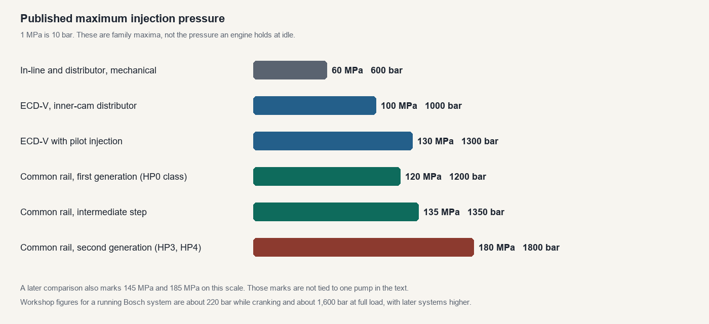
On a mechanical in-line pump or a distributor pump, injection pressure depends on engine speed, and the maximum pressure is limited by the pump itself. Pilot injection, and more than one injection in a stroke, are difficult. An electronically controlled distributor, the ECD-V series, added an electromagnetic spill valve so each cylinder’s quantity could be trimmed, and later versions added an inner-cam pump and pilot injection. The published maxima for that family step through 60 MPa, 100 MPa and 130 MPa. 1 MPa is 10 bar.
A common rail stores the pressure. The supply pump keeps the rail charged. The injector, not the pump cam, decides the moment of injection. Injection pressure can stay high at low engine speed, which is where a distributor pump is weakest, and the controller can fire a small pilot before the main injection. Black smoke on start-up and during acceleration falls because the spray is finer and the quantity is no longer tied to a rising cam.
The systems in use
Four manufacturers put a pressurised-fuel common rail into production: Bosch, Denso (earlier Nippondenso), Delphi and Siemens. Denso’s commercial truck system dates from 1995. The passenger-car pump, the HP2, followed in 1999, the lighter HP3 in 2001, and the three-plunger HP4 in 2004. Bosch, Siemens and Delphi each sold their own pumps, rails and injectors. The parts do not interchange, and a return-quantity limit written for one injector will condemn a good injector of another make.
| System | How rail pressure is set | Injector | Controller, where this wiki has one |
|---|---|---|---|
| Bosch | Early pumps spill from the high-pressure side. Later pumps meter the fuel taken into the pumping elements. CP1H and CP3 use a gear feed pump and run the inlet under a slight vacuum. | Solenoid, or piezo on the third generation. Piezo return is held at about 10 bar. | EDC15 common-rail variants, EDC16, EDC17, MD1. The C and CP suffixes are the common-rail branches. Unit-injector EDC16s are a different fuel system. |
| Denso | HP0 meters with a pump control valve on the plunger’s pre-stroke. HP2, HP3 and HP4 meter with a suction control valve, so the pump only compresses the volume the rail needs. | Solenoid two-way valve. Generations X1, X2 and G2. Later injectors carry a QR code instead of a correction resistor. | A Denso engine ECU. Many applications add an EDU, a separate high-voltage injector driver. Some ECUs contain that charge circuit and have no EDU. |
| Delphi | Its own high-pressure pump and rail hardware. Low-pressure and return figures have to be taken from that system’s procedure. | Solenoid injectors trimmed by a C2i code written into the controller for the cylinder the injector is fitted to. | Delphi diesel controllers. Treat a C2i code as injector calibration, not as a tune. |
| Siemens | Its own pump and rail. The injector return must stay at the pressure that injector was designed for. | Piezo stack. Opening and closing are opposite polarities. Families include 5WS40000 and 5WS40148 / 5WS40149. | Siemens diesel controllers, later associated with Continental. Do not use the petrol Siemens MS and Simos pages for these injectors. |
Bosch’s own vehicle examples already on this wiki are narrower than the family labels. The Volkswagen 3.0 V6 TDI case on EDC16 injection systems is an EDC 16 C common rail with a high-pressure range of 300 to 1,600 bar, piezo injectors, a pressure sender, a pressure-regulating valve and a fuel-metering valve, and a 10 bar injector return. The Audi 2.7 TDI example there is an EDC-16CP+ system with a stated maximum of 1,600 bar. Those figures belong to those installations. EDC17 Audi 2.0 TDI is the later Bosch controller on a different engine.
What the controller commands
The engine ECU reads crankshaft speed, cylinder recognition, accelerator position, temperatures, intake pressure and, where fitted, air mass. It then commands three things that used to be mechanical: rail pressure, injection timing and injection quantity. Because those three are independent of a pump cam, several injections in one stroke are normal.
- Pilot injection puts a small quantity in before the main. High pressure would otherwise put too much fuel in during the ignition delay, and that fuel would burn at once. The result of that burn is diesel knock and NOx. The pilot shortens the delay and cuts the noise.
- Split injection on a cold start breaks the early fuel into two or more very small pulses before the main, to help the engine light.
- Multi-injection on later injectors adds small pulses before and after the main, up to four extra pulses on some maps, without changing the total quantity. A five-pulse pattern is pre-injection, pilot, main, after-injection and post-injection.
Quantity is the lesser of two calculations. One is the governor quantity, from accelerator position and engine speed: more pedal gives more fuel, and at a fixed pedal a rising engine speed gives less. The other is the maximum quantity, from engine speed, reduced or increased for coolant temperature, fuel temperature, intake temperature, intake pressure, atmospheric pressure and, on a first-generation HP0 only, a selected full-load resistor. There are 15 of those resistors. The manufacturer fits the one that brings that pump to the full-load standard. During acceleration a large pedal change is delayed on purpose, so the fuel does not arrive before the air and make black smoke. Starting quantity is a separate map, increased when the coolant is cold, and it is cancelled once the engine has started.
Main timing starts from engine speed and the final quantity, then moves for battery voltage, intake pressure, atmospheric pressure, intake temperature and coolant temperature. Pilot timing is a calculated interval before that main pulse. The interval during cranking comes from coolant temperature and speed. Rail-pressure demand comes from the final quantity and engine speed once the engine is running, and from coolant temperature and speed while it is starting.
Idle speed is fuel quantity, not a throttle stop. The target depends on coolant temperature, whether the transmission is automatic, the gear position and the air-conditioning load. Some installations still have a manual idle setting. A separate idle-balance function compares the angular time of each cylinder and trims that cylinder’s quantity when one is slow. That trim is a symptom. It is not, by itself, proof that the injector is the failed part. Low compression and a valve that does not seal move the same number. See EDC15 diagnostic data for the earlier form of the comparison, and fuelling faults for how to read it.
Operating pressures
A number is only useful with the condition it was measured under. These are the published bands, not a target to tune to.
| Condition | Pressure | What it belongs to |
|---|---|---|
| Cranking, minimum for the engine to be able to run | About 220 bar, and a sound Bosch pump on a start-capacity test reaches at least 250 bar | Workshop cranking checks. The 250 bar figure is measured at the pump outlet with a calibrated leak standing in for the injectors, and the test module limits the reading at 500 bar. |
| Idle and light load | Often a few hundred bar. One Toyota running-engine monitor expects the displayed value, after a warm-up, to lie between 30 and 160 MPa (300 to 1,600 bar). | That span is the normal running band of that monitor. It is not an idle setpoint. |
| Full load, passenger-car systems of the 1,600 bar generation | About 1,600 bar (160 MPa) | The general full-load figure, and the top of the Volkswagen 3.0 V6 and Audi 2.7 examples. |
| Second-generation Denso (HP3, HP4) maximum | 180 MPa (1,800 bar) | Family maximum injection pressure. |
| Later systems | Up to about 2,200 bar can be present | Treat every joint as if that pressure is still there after the engine has stopped. |
| Cummins common rail, injectors enabled | About 5,000 psi (345 bar) before the injectors are fired. Idle about 5,000 psi. Wide-open throttle up to about 30,000 psi (about 2,070 bar). | That cranking threshold is why a leak that empties the rail stretches a normal three-to-five-second start. It is this system’s threshold, not a Bosch passenger-car start map. |
| Pressure limiter, rail | Opens at about 140 to 230 MPa and reseats at about 30 to 50 MPa | The exact pair depends on the vehicle. Fuel from the limiter returns to the tank. |
| Low-pressure supply | Electric feed pump 2.0 to 2.5 bar while cranking. Gear feed pump on CP1H and CP3: a suction of 0.10 to 0.20 bar. Filter inlet-to-outlet difference above 0.3 bar means the filter is blocked. | Measured with a low-pressure gauge. A high-pressure gauge does not belong on this pipe, and a petrol gauge does not belong on the rail. |
| Injector return | 0.6 to 0.9 bar on a first-generation Bosch system, measured between the collector and the tank. About 10 bar on a third-generation Bosch piezo system. | The first figure is what opens the pump safety valve. The 10 bar figure is required for the piezo injector to operate. Holding it needs the adaptor made for that return. |
Rail, limiter and sensors
The rail is a store. Its shape changes with the engine, but the parts are the same kinds of part: a pressure sensor, a pressure limiter, and on some engines a flow damper or a pressure-discharge valve.
The limiter is a mechanical relief. If rail pressure runs away it opens and dumps fuel to the tank, then shuts again once the pressure has fallen. The sensor is a semiconductor element on a 5 V supply. Some rails have two sensing elements with offset outputs, so a single failed element can be detected. The ECU closes the pressure loop on this signal. A sensor that reads low will drive the pump harder. Comparing the sensor with a mechanical gauge, using the high-pressure procedure, is the test that separates a bad sensor from a bad pump.
A flow damper sits in the pipe to an injector, mostly on larger engines. A normal pressure pulse moves its piston and the piston returns. An abnormal flow, from a split pipe or an injector that is pouring fuel, drives the piston onto its seat and shuts that pipe off. The leak then stops, which is easy to misread as a pipe that was never leaking. Passenger-car rails more often use a solenoid pressure-discharge valve: the ECU opens it when rail pressure is above the target and the fuel returns to the tank.
On an HP0 the cylinder-recognition sensor is on the pump camshaft. On HP2, HP3 and HP4 it is by the pump timing gear. Combined with the crankshaft sensor it tells the ECU which cylinder is which. The crankshaft sensor is a magnetic pickup. The cylinder sensor is either the same kind of pickup or a magnetic-resistance element with its own amplifier. Loss of either signal is a no-start or a stall, and it looks like a fuel fault because no injection is commanded.
Fuel, cleanliness and injury
The pumping elements and the injector clearances are lubricated by the fuel. Petrol in a diesel tank destroys that lubrication. Water in the sedimentor does the same, more slowly. A blocked filter, or a gauze screen full of debris, starves the high-pressure pump and the pump is then blamed. Dirt that enters an opened joint is enough to ruin a pump and a set of injectors. Open the system only after it has been depressurised, cap every port, and do not reuse a suspect high-pressure pipe.
Rail pressure will inject through skin. Wait out the depressurising time in the vehicle procedure before cracking a joint. Thirty seconds is the minimum quoted for one Bosch solenoid procedure. The vehicle in front of you may need longer. Do not use a cap, a plug or a finger as a substitute for the blanking tool made for a high-pressure port.
Petrol direct injection is a rail as well
A petrol direct-injection engine has the same split, at much lower pressure. An in-tank pump feeds a cam-driven high-pressure pump, and that pump feeds a rail and the injectors in the head. Current Bosch systems are described at up to 6 bar into the high-pressure pump and up to 350 bar in the rail. The low-pressure side is often returnless: the pump is driven with a pulsed supply, so a voltmeter on the pump wire jumps around instead of sitting at battery voltage. Loss of communication with the pump module can shut the pump off even though the pump itself is sound. The failure modes and the tests are on fuel pump faults and the test page.