Many common-rail injectors use a hydraulic control chamber. An electrical actuator operates a control valve; changing pressure above the nozzle needle allows it to open or close. The exact mechanism varies by injector design. Controlled return flow is normal, while excessive internal leakage can prevent rail pressure building and cause a long crank or no-start. That test is on injector faults and common-rail fuel system tests.
For off-vehicle test plans and measured delivery and return, see common-rail diesel injector bench testing.
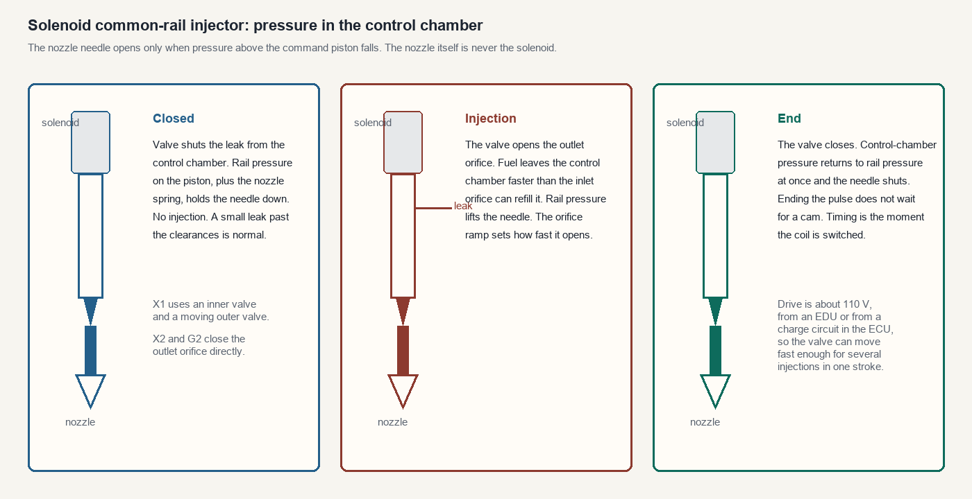
Denso solenoid injectors
The Denso X1, X2 and G2 families are examples of solenoid common-rail injectors. They use a nozzle, a control orifice, a command piston and a two-way valve; details and pressure ratings differ by design.
| Type | Valve | What changed |
|---|---|---|
| X1 | A fixed inner valve and a moving outer valve. The outer valve is held on its seat by a spring and by fuel pressure. | First generation. Pilot injection. Associated with the 120 MPa systems. |
| X2 | The solenoid opens and closes the outlet orifice directly. | Smaller, less drive energy, tighter quantity control. The outlet orifice is no longer closed by a separate outer valve. |
| G2 | Same direct outlet-orifice valve as the X2, with a body built for higher pressure and faster operation. | Second generation, 180 MPa. Multi-injection: the main quantity can be split into one to five injections. A typical pattern is pre-injection, pilot, main, after-injection and post-injection. |
With the valve de-energised, control-chamber pressure and the pressure under the needle are both rail pressure. The piston area and the nozzle spring keep the needle shut. Energising the valve opens the leak. The outlet orifice is larger in effect than the inlet orifice, so chamber pressure falls, the needle rises, and the rising rate follows the orifice rather than jumping open. Fuel that leaves the control chamber returns to the tank. Ending the current closes the leak, chamber pressure recovers, and the needle shuts sharply. That sharp end is why injection timing is the electrical pulse, not a cam.
In the Denso solenoid examples described here, an ECU charging circuit or separate EDU can raise battery voltage to approximately 110 V and then control the injector current. This is not a universal drive voltage. The EDU returns an injection-verification signal to the ECU. On a four-cylinder ECU-driven layout the outputs are the four injector lines. On an EDU layout the ECU sends timing signals in and the EDU drives the injectors, often grouped onto two commons. A missing verification signal warrants the specified driver, injector and wiring checks; it does not by itself identify the failed part or nozzle condition.
Two mechanical details change how the injector is diagnosed.
- A hollow screw with a damper on the leak port quiets pressure pulses in the return and reduces the effect of return-pipe pressure on the injected quantity. A crushed leak hose changes the quantity even when the command pulse is unchanged.
- Early connectors contain a correction resistor, read by the ECU, so cylinder-to-cylinder scatter is trimmed in the pulse. Later injectors carry a QR code. The code holds quantity-correction points across pressure and pulse width, plus the part number and the product number. The ECU does not read that resistor, because there is not one. The code is written into the ECU.
On systems using these Denso correction codes, enter the replacement injector's code for its cylinder and follow the ECU-replacement procedure for registering all fitted injectors. Leaving the previous code in place gives a quantity error on a good injector. The code is calibration of that part. It is not a performance map.
Bosch solenoid and piezo injectors
Bosch solenoid injectors use a control-chamber principle. Return flow is normal; excessive internal leakage can reduce available rail pressure. Test duration, temperature, pressure and allowed quantity or imbalance depend on the specific system and procedure. One high-return injector is a lead for further investigation, not proof of its exact failure or proof that the pump is healthy. Some return circuits require back-pressure and cannot be tested with open bottles. See on-vehicle injector testing and Pico's test limitations.
Some Bosch piezo systems require a pressurised return and a test adapter that maintains the specified back-pressure. Venting them into an open bottle written for a solenoid injector is the wrong test. The electrical drive is high voltage. Use the procedure for the injector that is fitted.
Bosch IMA and Delphi C2i are examples of injector correction codes. Where required, enter the fitted injector's code in the correct cylinder position and follow the application procedure. An incorrect code can affect fuelling. It does not compensate for a cracked body or a nozzle that dribbles.
Siemens piezo injectors
A piezo actuator changes shape when a voltage is applied, and it stays in the new shape until a voltage of the opposite polarity is applied. On these injectors each ceramic sheet is 80 μm thick and grows by about 0.13 μm. One sheet is useless as a valve motor, so the actuator is a stack of about 350 sheets. The stack’s maximum movement is about 40 μm. That movement is faster than a solenoid of the same size, which is why the injected quantity can be controlled more tightly and the smoke falls.
The stack is a motor, not a sensor. Both the opening and the closing are commanded. If the connector is pulled while the engine is running, the injector can remain open. An injector left open will fill the cylinder and can destroy the engine. Do not disconnect a Siemens piezo injector on a running engine.
Two constructions are in service. The part numbers are on the injector.
| Family | How the stack moves the valve |
|---|---|
| 5WS40000 | The stack bears on a shim and a control lever. The lever moves a valve piston. Below that are the mushroom valve and its spring, the driving spindle, the nozzle spring and shim, the nozzle plunger and the nozzle, held by the nozzle nut. A copper heat shield sits on the nut. |
| 5WS40148 and 5WS40149 | No control lever. A castellated nut and a driving valve pin sit under the actuator shim. The mushroom valve, spindle and nozzle are the same kind of hydraulic stage. |
Electrical and insulation checks, component serviceability and any disassembly or cleaning procedure depend on the exact injector and equipment. Refer the injector to a suitably equipped specialist using the applicable manufacturer's repair and test plan; do not generalise cleaning or repair instructions across families. Delphi: electrical checks for its injectors.
Valve sealing, actuator condition and delivery require specialist equipment and the test plan for the exact injector. Pressurised spray can penetrate skin. Do not apply an unverified pressure or leak-down limit to a piezo injector. See diesel injector bench testing.
The nozzle, spindle, springs and shims are a matched stack. Shims set the lifts. Mixing them between injectors, or leaving one out, changes the quantity and the response. After assembly the injector goes back on a bench that can drive the piezo stack in both polarities and measure delivery. A solenoid bench programme is the wrong driver.
When the injector is the fault, and when it is not
Symptoms that start this job are a hard start, an uneven idle, a hesitation, smoke, or a lack of power. All of them are also caused by low rail pressure, air in the feed, a blocked filter, a bad connector and low compression. A contribution code, abnormal balance or unusual return directs attention to a cylinder but does not by itself identify the failed component. A supply or pump fault can affect all cylinders; a single leaking injector can also keep the whole rail below the starting threshold.
Depending on the engine and where an injector leaks, a defect can cause long cranking, pressure loss, misfire or fuel dilution of the oil; these findings are not unique to a cracked injector. Some vehicle-specific procedures use approved high-pressure isolation equipment. Use the exact manufacturer procedure and qualified equipment; starting thresholds and expected crank times vary. See fuel-system tests.
A leaking nozzle can admit unwanted fuel to a cylinder, potentially causing combustion symptoms or fuel dilution. Fuel dilution can also be associated with regeneration strategies or other leaks; symptoms alone do not identify the cause. Both have to be considered before the injector is condemned. See particulate filter faults.
Deposits can restrict injector delivery, but symptoms and the amount of restriction that causes a fault vary by engine and test conditions. For petrol injectors, use an appropriate balance or bench test, and check the correct part number as well as fuel pressure and ignition. See injector diagnosis and fuel trims.
An electrical fault at the connector imitates a failed injector. Brittle connectors break when they are pulled. A code for one cylinder that appears when the harness is moved points toward a connection or wiring fault that needs confirmation. An electrically faulty injector or wiring may affect a shared driver, depending on the circuit. Use the manufacturer's tests and specifications with the circuit safely isolated; resistance alone does not prove spray or fuel delivery. Piezo and solenoid tests differ.