The high-pressure pump is the part that fills the rail. It does not time the injection and it does not meter the cylinder. A feed pump, electric in the tank or mechanical on the high-pressure pump, has to deliver clean fuel to it first. If the feed pressure is wrong, the high-pressure pump cannot fill the rail, and a new high-pressure pump will fail the same way. How that failure looks on the engine is on fuel pump faults. The system around the pump is on common-rail diesel fuel systems.
Feed pumps
The feed pump draws from the tank, through the filter, and charges the high-pressure elements. Two mechanical types are used inside Denso supply pumps.
- Trochoid. Inner and outer rotors, driven by the pump shaft. The space between them opens on the suction port and closes on the discharge port. Used on the HP0 and the HP3.
- Vane. A rotor in an eccentric ring, with vanes that slide out against the ring. The HP2 uses four vanes, each with a spring behind it so the vane still seals at low speed. The HP0 is also built with a vane feed pump.
A regulating valve, or an overflow valve on the HP0, spills feed pressure back to the suction side once it exceeds the spring setting. That keeps the pressure on the suction valve from rising with pump speed. The fuel-temperature sensor on HP2, HP3 and HP4 is a thermistor on the inlet of the supply pump. On an HP0 it is on an injector leak pipe instead.
Low-pressure arrangements differ. Some systems use an electric lift pump; others draw fuel through a pump-mounted feed stage. Use the vehicle-specific pressure or vacuum limits, measuring point and cranking or running conditions. Bubbles in an approved transparent test section can indicate air ingress, but also check the test connections, priming and system layout before deciding on a cause. Delphi: supply restriction and pressure checks.
Compare filter pressure drop with the vehicle-specific limit under its prescribed test conditions. A priming pump that weeps, a piston that stays proud, or a loose primer joint lets air in. Water in the sedimentor is drained before the pump is asked to run on it. A gauze screen at the pump inlet, packed with debris, is cleaned or the filter and pipes are replaced. Do not treat a dirty screen as a reason to fit a pump and leave the debris in the tank.
Denso HP0
The HP0 is the first Denso common-rail pump, used on large trucks and buses. It is a two-cylinder cam pump, turning at half engine speed, with a feed pump, a delivery valve, an overflow valve and a cylinder-recognition sensor on the camshaft. The number of cam peaks is chosen so that the pump delivers once for every injection. A four-cylinder engine uses two peaks and four deliveries in two engine revolutions. A six-cylinder engine uses three peaks and six deliveries. An eight-cylinder engine uses four peaks and eight deliveries. Matching the deliveries to the injections keeps the rail pressure even.
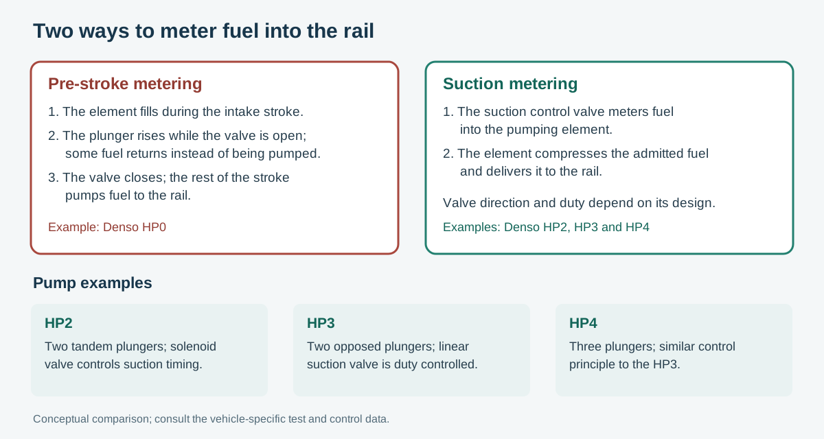
Rail pressure is set by the pump control valve, one on each element. During the plunger’s descent the valve is open and the element fills. At the start of the rise the valve is still open, so fuel returns through it and is not compressed. This is the pre-stroke. When the ECU energises the valve it shuts, pressure rises, and the delivery valve passes fuel to the rail. Closing the valve earlier lengthens the pumping part of the lift and raises delivery. Closing it later shortens delivery. The quantity is the plunger area times the lift that happens after the valve has shut. When the cam passes its peak the delivery valve seats, the control valve opens, and the element fills again.
The control-valve relay is fed from the ignition switch. The ECU times the ground. A valve that cannot close cannot make rail pressure. A valve that stays closed tries to deliver the full stroke.
The recognition sensor reads a disc on the pump camshaft. On a six-cylinder pump the disc has cutouts every 120 degrees plus one extra cutout, so it produces seven pulses in two engine revolutions. The pulse that follows the extra cutout, read together with the crankshaft pulses, is cylinder 1.
Denso HP2
The HP2 replaced the ECD-V3 on passenger cars and four-wheel-drive vehicles. It is shorter and the drive torque is halved by using two plungers in tandem, one horizontal and one vertical, inside one inner cam. Each plunger delivers twice for every turn of the pump, so one revolution sends four deliveries to the rail. The two plungers are opposite: when one is filling, the other is pumping. Peak torque is about half that of a single plunger with the same capacity. The pump still turns at half engine speed.
The inner cam and the shaft are one piece. Cam lift is 3.4 mm. The rollers are reinforced ceramic, 9 mm in diameter and 21 mm long. One plunger is a pair of medium-length parts. The other is a short part and a long part. A delivery valve with two balls connects the two plungers to the rail on alternate strokes. A check valve between the suction control valve and the elements stops compressed fuel being pushed back into the suction valve.
The HP2 uses two on/off suction-control valves, one for each pumping system. Energising a valve opens its passage; de-energising it closes the passage. Denso: HP2 and HP3/HP4 suction valves. The ECU leaves the start of suction fixed, from the crankshaft signal, and moves the moment the valve turns off. Turning it off early reduces the fill. Turning it off late increases the fill. Fill equals delivery, because only the fuel that was admitted is compressed. Except at full fill, the roller leaves the cam when suction ends and meets the cam again when the lobe comes round. That is different from the HP3, whose plungers are sprung onto the ring cam and follow it.
Because fuel that is not needed is never compressed, the pump runs cooler and takes less torque. The feed pressure is held down by the regulating valve before it reaches the suction valve.
Denso HP3
The HP3 is the compact pump for passenger cars and small trucks. An eccentric cam on the shaft moves a ring cam up and down. The ring cam does not rotate. Two plungers sit opposite each other on the outside of the ring. The pump is driven at engine speed or at half engine speed, depending on the installation. A trochoid feed pump and a regulating valve supply the plungers through the suction control valve and a suction valve. Each plunger has its own delivery valve, a ball and spring in the element, which opens only when plunger pressure exceeds rail pressure.
The suction valve is a linear solenoid under duty-cycle control, not the simple on/off valve of the HP2. The ECU sends a fixed-frequency pulse. The average current sets the needle position and therefore the flow. There are two families, and they fail in opposite ways if the connector is off:
- Normally open. With no current the spring holds the passage fully open and the pump takes a full charge. Current pushes the needle (or, on the compact valve, pulls it) towards closed. A short on-time gives a large opening and more fuel. A long on-time gives a small opening and less fuel. With the valve disconnected, it defaults towards its open, maximum-fill position; actual rail pressure still depends on supply, pump speed, leakage, other controls and ECU response.
- Normally closed. Current opens the passage. No current lets the spring shut it. A long on-time gives more fuel. A short on-time gives less. With the valve disconnected, it defaults towards the closed position and prevents normal fuel supply to the pumping elements.
The compact suction valve puts the return spring and the needle the other way round, so the needle is pulled rather than pushed. The duty relationship still follows whichever family the valve belongs to, normally open or normally closed. Identify the valve before deciding what a full or zero duty should do.
During the fill stroke the plunger spring follows the ring cam down, so the plunger itself draws fuel in. The suction valve has already limited that volume. The following rise pumps it. On some DPNR installations an exhaust fuel-addition valve supplies fuel for aftertreatment, and an HP3 can carry a flow damper on that passage. If the passage leaks, the damper shuts and stops the leak. A fuel-addition valve that has gone quiet is not always a valve that has failed electrically.
Denso HP4
The HP4 is an HP3 with three plungers instead of two, for medium trucks and other larger engines. The plungers sit at 120 degrees around a triangular ring cam. Capacity is one and a half times the HP3. Feed pump, regulating valve, suction control valve, suction valves, delivery valves and fuel-temperature sensor are the same parts doing the same jobs. The eccentric cam moves the ring, the ring does not rotate, and duty-cycle control of the suction valve sets the fill exactly as on the HP3.
Bosch high-pressure pumps
Bosch CP1H and CP3 pumps use inlet metering on documented systems. Feed-pump configuration, inlet pressure or vacuum, and acceptance limits depend on the actual installation; check the vehicle procedure. Bosch: pump generations.
Some early Bosch passenger-car systems regulate rail pressure on the high-pressure side; other generations use inlet metering or a combination of controls. Some Bosch piezo systems require a pressurised injector return. Return layout and specification are application-specific; do not apply an open-return test where back-pressure must be maintained. Pico: return-test limits.
A pump capacity test is a specialist procedure: use the equipment, calibration, prescribed conditions and acceptance limit for that pump and vehicle. Check supply, cranking speed and controls as specified. If an independent rail-pressure reading disagrees with the ECU, also check the reference instrument and sensor supply, ground and signal before replacing parts. Delphi: scoped no-start diagnosis. The Volkswagen 3.0 V6 example uses both a metering valve and a pressure-regulating valve, with a working range of 300 to 1,600 bar. That combination is described on EDC16 injection systems.
Later Bosch pumps meter on the inlet, in the same spirit as the Denso suction valve: only the required volume is compressed. Which valve a given engine uses, and what duty means on it, comes from that engine’s wiring and the live data, not from the pump looking similar.
The CP4 is the later Bosch high-pressure pump, built as CP4.1 with one plunger and CP4.2 with two. Its roller runs on a shoe, and the fuel is the oil film in that bearing. How that film fails, and why the metal then fills the rail, is on Bosch CP4 pump failures.
Delphi and Siemens pumps
Delphi and Siemens common-rail engines use their own high-pressure pumps, feed pumps and rails. The low-pressure test, the cranking-pressure test and the return test are the same ideas as on a Bosch or Denso system, and the numbers are not. A gear-pump suction figure taken from a CP3, or a 10 bar piezo-return figure taken from a Bosch injector, does not transfer. Identify the pump and use its procedure. Injector coding for Delphi is the C2i code. Siemens injectors are the piezo parts on common-rail diesel injectors.
Petrol pumps that feed a rail
Port-injection petrol engines have one pump, in the tank, and a regulator. Older imports energised that pump with the key and regulated with a vacuum diaphragm. Later returnless systems vary pump speed from engine data, with different behaviour for start, acceleration, deceleration and fuel cut. Those modes show on enhanced scan data. The pump can be its own module on the serial bus, sharing level and tank pressure with the instrument cluster. If that bus is down, the pump can be shut off. A meter on a pulse-width-modulated pump supply may show an average or a changing reading depending on the signal and meter; use the appropriate test procedure.
Direct injection adds a second, mechanical pump on the camshaft. The in-tank pump only has to feed it, at a few bar. The mechanical pump makes the rail pressure, from a few tens of bar on early systems to about 350 bar on later Bosch systems. An early MED 7 layout ran the in-tank pump at about 3 bar, up to 5.8 bar on a hot start, and the rail at 50 to 100 bar. The diagnostic split is the same as diesel: compare low-side pressure with high-side pressure before replacing either pump. A low side that collapses under load will empty the high-pressure pump’s fill, and the high-pressure pump will be blamed.
The cam follower on some Volkswagen and Audi high-pressure pumps wears when the oil is neglected or has sheared. The follower runs on the cam lobe. A worn follower is an oil-supply and service-interval fault as well as a pump fault. Fitting a pump and leaving the oil that destroyed the follower repeats the failure. Neglected oil changes on a direct-injection engine also wear the lobe itself.
Use the vehicle-specific electrical, supply-pressure, flow and control tests. Injector pulse indication is not a substitute for a pump pressure or flow test; direct-injection circuits require equipment rated for their driver voltages. Rail-pressure decay can have several causes, including an injector, pressure-control component or leak, and does not by itself isolate the failed part. Delphi: pump electrical checks.
For the aftertreatment function of the fuel-addition system on some installations, see Toyota DPNR. Confirm the fuel circuit and test procedure for the specific vehicle.
More on Bosch CP3 pumps
Compare the Bosch CP3 family, R70 and R90, including part-number examples, fuel-system checks and M57 upgrade considerations.