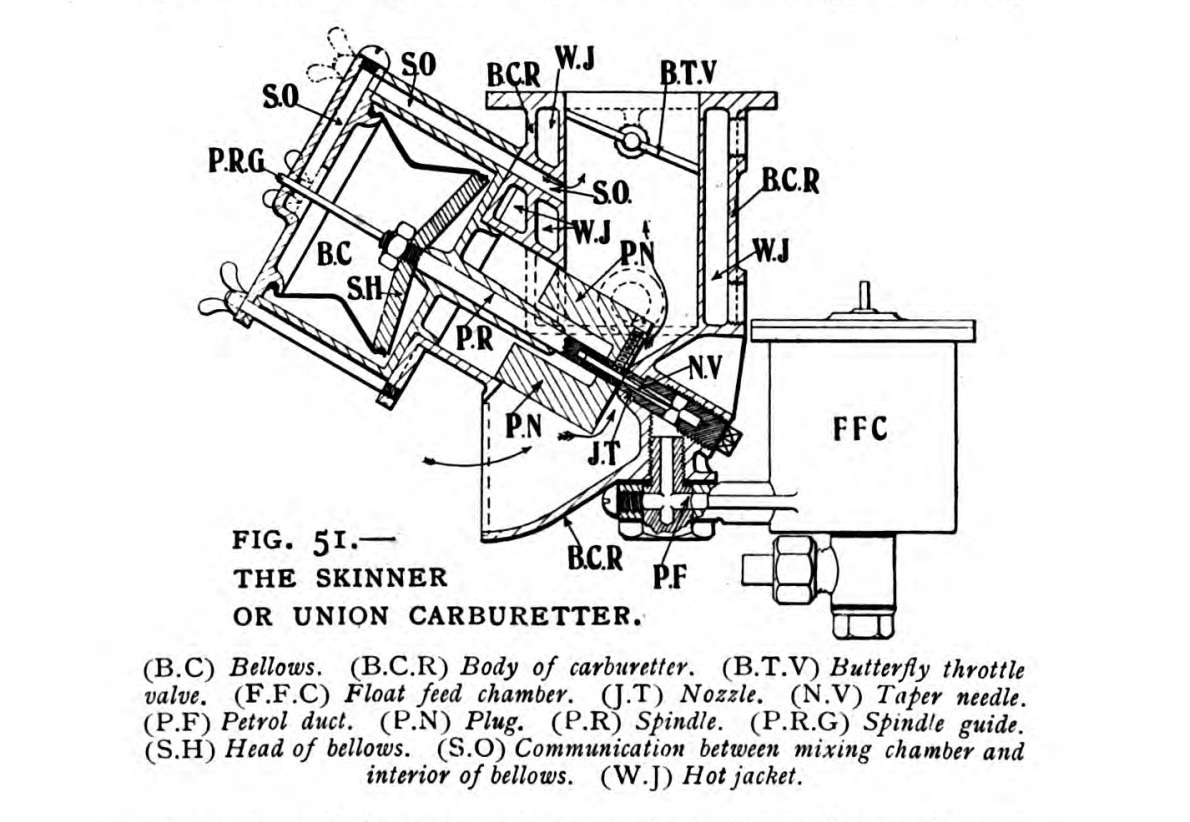
SU carburettors (originally Skinners Union, now manufactured and supported by Burlen Ltd) are variable-choke, constant-depression carburettors fitted to millions of British, Swedish and European cars and motorcycles from the early 20th century through the early 1990s. Every SU meters fuel through a single main jet whose effective area is varied by a tapered needle mounted beneath a rising vacuum piston.

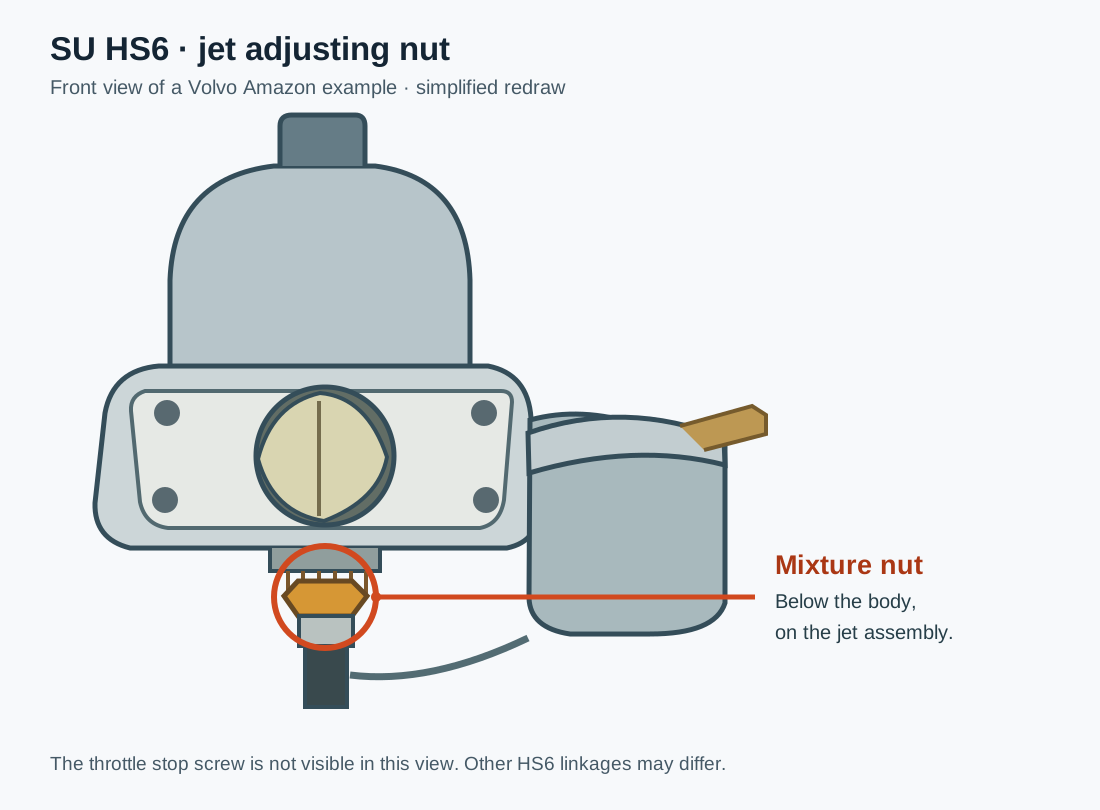

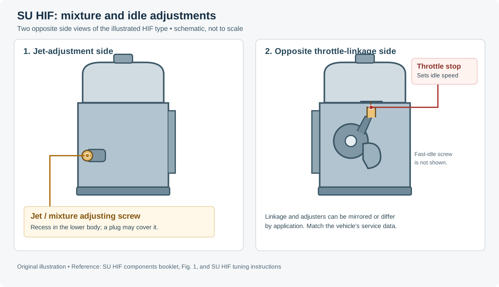
SU adjustment diagrams by type
Use the diagram for the carburettor fitted: linkage orientation and the controls differ between types and applications. These illustrations are hosted by SU Carburetters.
- H type: explanatory diagrams; see also the H-type tuning guide for throttle, jet nut and fast-idle adjustment.
- HD type: single-carb adjustment diagrams, including the slow-running valve, fast-idle screw and jet adjusting screw. On some multi-carb installations a throttle adjusting screw is used instead of the slow-running valve; see the HD multi-carb guide.
- HS type: throttle and jet adjustment diagrams. The first illustration identifies the idle-speed throttle screw (1) and mixture jet adjusting nut or screw (2); the later illustration identifies the fast-idle screw (4).
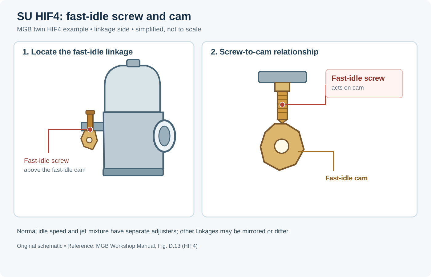
- HIF type: throttle and jet adjustment diagrams. The first illustration identifies the idle-speed throttle screw (1) and mixture jet adjusting screw (2); the later illustration identifies the fast-idle screw (4).
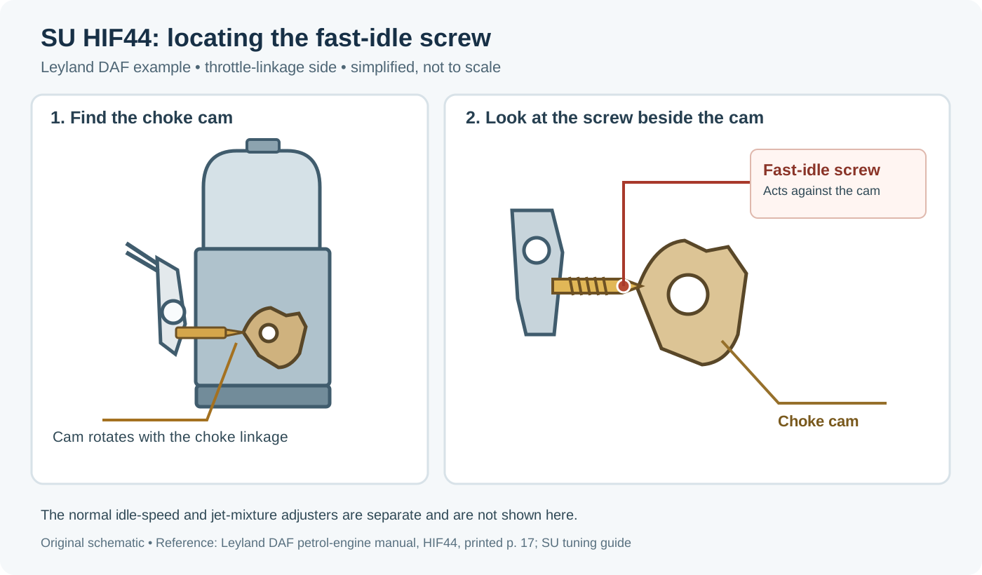

How SU identifies type and bore size
SU designations combine a letter prefix (identifying the body, float-chamber mounting and jet-seal generation) with a numeric suffix giving the throttle-butterfly diameter:
- Single-digit suffix (Imperial): indicates how many eighths of an inch the throttle bore exceeds 1 inch. For example,
H1= 1 + 1/8 in (1⅛ in),HS2= 1 + 2/8 in (1¼ in / 31.75 mm),HS4= 1½ in (38.1 mm),HS6= 1¾ in (44.45 mm), andHD8/HS8= 2 in (50.8 mm). EarlyHV0used 7/8 in (listed in BMC Service AKD 4789 J) and larger obsoleteHmodels reached 2¼ in and 2½ in. - Two-digit suffix (Metric, later HIF series): states the bore diameter directly in millimetres—for example
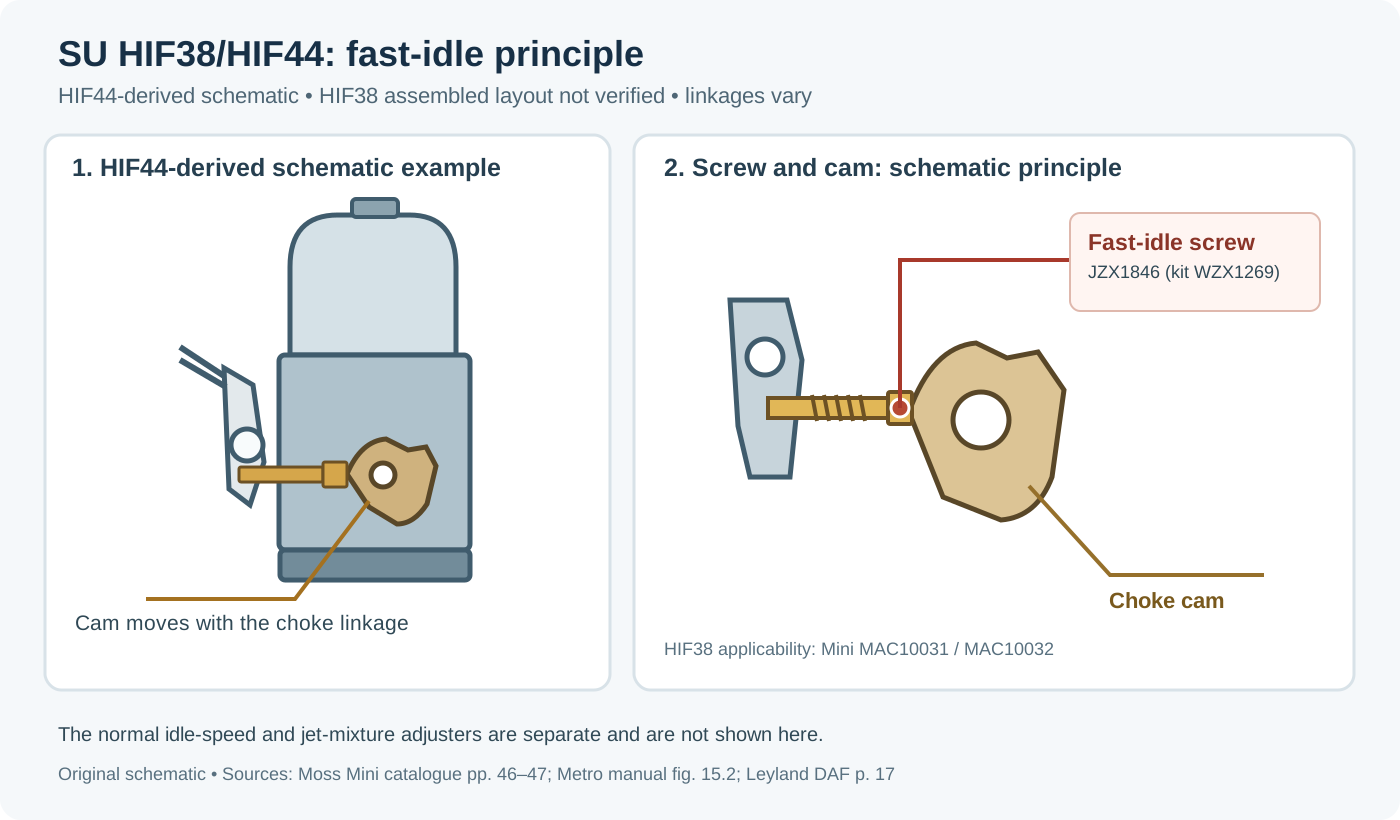
HIF38(38 mm, ~1½ in) andHIF44(44 mm, ~1¾ in). Earlier HIF models used the Imperial digit (HIF4,HIF6,HIF7= 1⅞ in).
All main SU carburettor types
| Type | Era / introduction | Float chamber & jet feed | Key mechanical differences & common sizes |
|---|---|---|---|
| HV & OM (and early M / D / U series) | Late 1920s–1930s (HV from 1929) | Side-mounted float chamber; early pre-H vertical/horizontal/sloper bodies. | Predecessors to the H series; early units lacked the later piston lifting pin and had a test hole below the piston. Sizes recorded in BMC AKD 4789 J include HV0–HV8, OM (1 in) and D2–D5 / D4L. |
| H (H1, H2, H3, H4, H5, H6, H8) | 1937 onwards | Separate side float chamber attached by a cast arm and hollow banjo/shoulder bolt; fuel passes through the arm into cork-gland-sealed jet passages. | Horizontal or semi-downdraught; solid or rubber-grommet float-chamber mounting; cold-start enrichment pulls the jet downwards via lever and fast-idle link. |
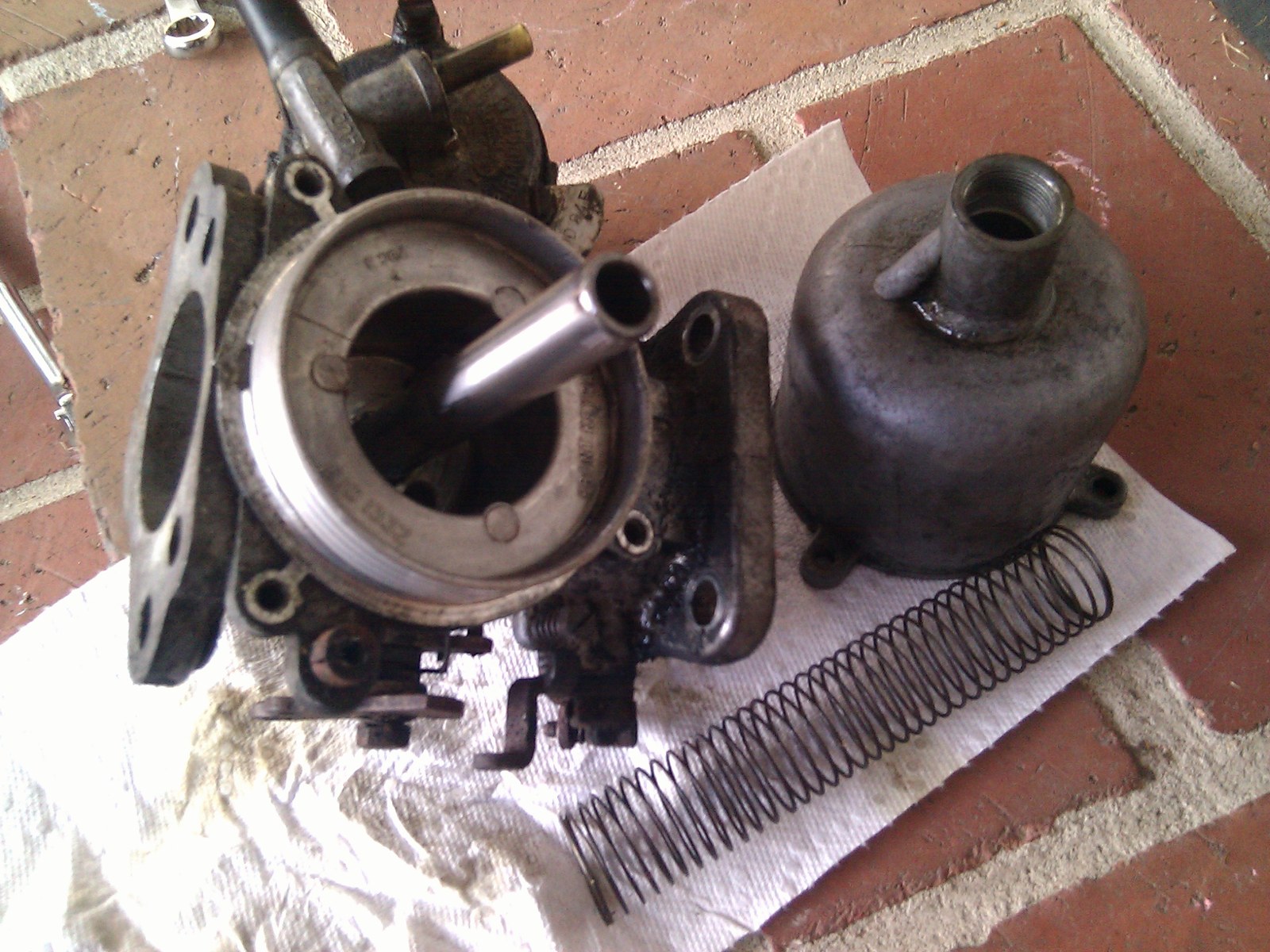
| HD (HD4, HD6, HD8) | 1954 onwards | Float chamber mounted concentrically directly below the main jet via a four-screw flange; sealed by a rubber diaphragm integral with the jet instead of cork glands. | Separate bypass idle passage so the throttle butterfly stays fully closed at idle; external mixture screw acting on a pivoted fork; horizontal or 30° semi-downdraught; no flexible float mount. |
| HS (HS2, HS4, HS6, HS8) | 1958 onwards | Side-mounted float chamber (rigid or rubber-mounted) feeding the bottom of the jet through an external flexible nylon tube. | "Horizontal Short body"; eliminates cork glands; vacuum advance port moved above throttle spindle; movable jet drops for cold-start choke; horizontal to 30° downdraught, LH or RH float bowls. |
| HIF (HIF4, HIF6, HIF7, HIF38, HIF44, HIF44E) | 1972 onwards | Horizontal Integral Float chamber cast underneath the body, concentric with the jet. | Built for emissions consistency: bi-metal fuel-temperature/viscosity compensator raises or lowers the jet; rotary-valve progressive cold-start enricher (jet no longer drops for choke); spring-loaded biased needle; part-throttle bypass emulsion; mountable horizontal to 40° downdraught. |
| DU6 | Late 1950s–early 1960s (very limited production) | Single central float chamber between two 1¾ in chokes (used narrow doped-cork float). | Rare twin-choke competition SU with diaphragm-operated full-throttle weakener to keep part-throttle and WOT mixtures aligned. |

Documented vehicle models and engines fitted
Exact SU specifications vary by model year, emission market and gearbox. Always confirm the tag or body specification before ordering needles or rebuild kits.
| SU type & configuration | Documented car models (examples) | Engines / capacities |
|---|---|---|
| Triple / Pair HV2, HV3, HV4, HV5 | Alvis Speed Twenty, Silver Eagle, Firefly, Crested Eagle (1930s) | Alvis 4-cyl & 6-cyl pre-war engines (recorded in BMC AKD 4789 J) |
| Single / Twin H1 (1⅛ in) | Austin-Healey Sprite Mk I ("Frogeye"), Triumph Herald 948 | BMC A-Series 948 cc; Standard SC 948 cc |
| Single / Twin H2 (1¼ in) | Morris Minor 1000 (early), MG TC / TD | BMC A-Series 948 cc; MG XPAG 1,250 cc |
| Twin H4 (1½ in) | MG TF, MGA 1500 / 1600, Austin-Healey 100 (BN1/BN2) & early 100-6 (BN4), Triumph TR2, Rover P4 (selected) | MG XPEG 1,466 cc; BMC B-Series 1,489 / 1,588 cc; Austin 2,660 cc 4-cyl & 2,639 cc C-Series 6-cyl; Triumph 1,991 cc 4-cyl |
| Twin H6 / H8 (1¾ in / 2 in) | MGA Twin Cam, Triumph TR3 / TR3A / TR4 (H6); Jaguar XK120 / XK140 (twin H6; twin H8 on C-head) | BMC B-Series Twin Cam 1,588 cc; Triumph 1,991 / 2,138 cc 4-cyl; Jaguar XK 3.4 L straight-six |
| Twin / Triple HD6 (1¾ in) | Austin-Healey 100-6 (late BN6) & 3000 Mk I (BN7/BT7), Jaguar XK150 & Mk II 3.4 / 3.8, Alvis (twin/triple HD6), Rover P4 (selected), Land Rover 109 2.6 (single) | BMC C-Series 2,639 / 2,912 cc; Jaguar XK 3.4 L / 3.8 L straight-six; Rover 2.6 L IOE six |
| Single / Twin / Triple HD8 (2 in) | Rover P5 3-Litre & Land Rover 109 2.6 (single), Austin-Healey 3000 Mk III BJ8 (twin), Bentley / Rolls-Royce Phantom VI & Corniche V8 (1971–72, twin), Daimler & Jaguar XJ6 1968–71 (twin), Aston Martin DB6 Mk II (triple), Jaguar XK150S & E-Type 3.8 / 4.2 (triple) | Rover IOE 2.6 / 3.0 L six; BMC C-Series 2,912 cc; Rolls-Royce 6.75 L V8; Aston Martin 4.0 L DOHC six; Jaguar XK 3.8 L / 4.2 L straight-six |
| Single / Twin HS2 (1¼ in) | Mini 848 / 998 (single), Mini Cooper & Cooper S (twin), Morris Minor 1000 (1960+, single), Austin/Morris 1100/1300 (single; twin on 1300 GT), Sprite Mk II–IV & MG Midget 948/1098/1275 (twin), Triumph Spitfire Mk I–IV (twin) | BMC A-Series 848 / 948 / 998 / 1,098 / 1,275 cc; Triumph 1,147 / 1,296 cc 4-cyl |
| Single / Twin / Triple HS4 (1½ in) | Mini 848/998 automatic & 1974+ 998 (single), Allegro 1100/1300 & Marina 1.3 (single), MGB 1962–71 (twin), Midget 1500 & Spitfire 1500 (twin), Triumph Dolomite 1850 & early 2000 TC (twin), Austin-Healey 3000 1961–62 (triple) | BMC A-Series 848–1,275 cc; BMC B-Series 1,798 cc; Triumph 1,493 cc, 1,854 cc slant-four & 1,998 cc six; BMC C-Series 2,912 cc |
| Single / Twin HS6 (1¾ in) | BMC 1800 Landcrab & Marina 1.8 (single), Maxi 1500/1750 (single; twin on 1750 HL), Rover P6 2000 (single), Volvo 122S / 140 / 1800S (twin), MGC & Austin-Healey 3000 Mk II BJ7 (twin), Jaguar 240 (twin), Triumph TR4A / TR7 UK / Dolomite Sprint / 2500 TC (twin), Rover P5B / P6 3500 V8 & early SD1 2300/2600 (twin) | BMC B-Series 1,798 cc & E-Series 1,485/1,748 cc; C-Series 2,912 cc; Volvo B18 / B20 1.8/2.0 L; Triumph 2,138 cc, 1,998 cc 16V & 2,498 cc six; Rover 2.0 L OHC, 2.3/2.6 L six & 3.5 L V8 |
| Twin HS8 (2 in) | Rover P6 2000 TC, Jaguar XJ6 & Daimler Sovereign 4.2 Series I/II (1971–75) | Rover 1,978 cc OHC four-cylinder; Jaguar XK 4.2 L straight-six |
| Twin HIF4 (1½ in) | MGB (1972 onwards, UK and most markets) | BMC B-Series 1,798 cc |
| Single / Twin HIF6 (1¾ in) | Princess 1700 / 2000 (single) & 2200 (twin), MGB GT V8 (twin), Rover P5B / P6 3500 V8 & early SD1 3500 (twin) | BL O-Series 1.7 / 2.0 L; E-Series 2.2 L six; Rover 3.5 L V8 |
| Twin HIF7 (1⅞ in) | Jaguar XJ6 4.2 (later carburetted models) | Jaguar XK 4.2 L straight-six |
| Single HIF38 (38 mm) | Mini 1.3 (early 1990s), Austin/MG Metro 1.0 | BMC A-Plus 998 cc & 1,275 cc |
| Single / Twin HIF44 (44 mm) | Metro 1.3 & MG Metro 1300 (single), Allegro 1300 1980+ (single), Austin Ambassador 1700/2000, Rover SD1 2300/2600 1982+ & 3500 V8 / Land Rover V8 / Range Rover & Discovery V8 1986+ (twin) | BMC A-Plus 1,275 cc; O-Series 1.7/2.0 L; Rover 2.3/2.6 L six & 3.5 L V8 |
| DU6 (dual 1¾ in) | Coventry Climax competition installations (Lotus Seven, Cooper Climax formula cars) | Coventry Climax 1.5 L FPF twin-cam competition four-cylinder |
Cold-start systems across SU types
- Manual jet-drop choke (H, HD, HS): pulling the dashboard choke cable first opens the throttle slightly via lost-motion linkage (fast idle) and then physically lowers the main jet (or diaphragm assembly on HD) away from the tapered needle to richen the mixture.
- Rotary enrichment valve (HIF): the main jet moves vertically only for mixture setting (via a screw acting on the bi-metal lever); cold-start enrichment comes from an auxiliary rotary valve with a tapered groove feeding extra fuel-air mixture into the constant-depression zone (Burlen HIF features).
- Thermo & AED (Automatic Enrichment Device): fitted to selected Jaguar, Austin/Morris, Daimler and Rover automatic/saloon installations—either an electrically/exhaust-heated bi-metal Thermo attachment or a separate auxiliary starting carburettor (AED) controlled by manifold vacuum and coolant/exhaust temperature.
Core tuning components on an SU
- Jet height / mixture nut (or screw): sets the idle datum position on the cylindrical root of the needle, shifting the entire fuel curve slightly richer or leaner.
- Tapered needle: machined to specific diameters at 1/8 in stations (fixed needles on older carbs; spring-loaded biased needles on later HS/HIF carbs). Changing needle profile alters mixture at specific piston lifts without changing the idle datum. See the SU needle profile database for 623 station profiles and the downloadable PDF chart.
- Piston return spring: colour-coded springs (blue, red, yellow, green, etc.) set the depression required to lift the piston, controlling when the piston reaches full lift relative to peak RPM.
- Oil damper: SAE 20 (up to SAE 30) oil inside the hollow piston rod resists rapid upward piston snap, creating brief enrichment during acceleration without a separate accelerator pump (Burlen SU technical guide).
Related pages
- SU carburettor troubleshooting, servicing and mixture adjustment
- SU needle profile database (623 profiles & PDF)
- Carburettors (section overview)
- Carburettor makes and model families
- Carburettor types and layouts
- Carburettor tuning, jetting and setup
- Carburettor synchronisation, faults and rebuilds
Sources
- Burlen Ltd / SU Carburetters: The SU Carburetter — Design, Function & Tuning Insights (P.G.G. Knight). H, HD, HS and DU6 design details, piston springs, oil dampers and tuning procedures.
- Burlen Ltd: SU Carburetter Design Features and HIF Design, Adjustment & Fuel Compensation.
- SU Carburetters: Fixing Idle and Rich Mixture Issues in HS Carburetters and HD Type Routine Servicing.
- S.U. Carburetter and Pump Specifications — Cars (BMC Service AKD 4789 J / AUC 9631 J, 1968) and SU / Butec 1969–1983 Catalogue.
- SU Specialists: Which SU Carburettor Fits My Classic Car, SW-EM Volvo HS6 reference, and Burlen Phantom VI / Corniche HD8 listing.
- The SU Carburetter and Fuel Pump Workshop Manual. The SU Carburetter Company, 1958.