BMW workshop diagnosis is a chain, and the chain changed more than once. A screen asks the questions. A head on the car translates them onto the socket. A server, or a disc in the tester, holds the test plans and the software to be loaded. Measurement sits beside that chain, and it is allowed to change the next question. Coding and programming are not the same job, and for several years they did not even run on the diagnostic tester.
The equipment pages listed from BMW diagnostics name the boxes. This page is the order they were used in, and what each generation was trusted to do. A date below belongs to the generation it is written against. A later car does not inherit an earlier tester just because the plug still fits.
The job, before the tool
The method taught for every BMW, regardless of tester, has five steps. Confirm the complaint by reproducing the symptom, including the road, the temperature and how often it happens. Analyse it from the fault memory, the function description, the repair history and any known measure for that car. Isolate it by deciding whether the fault is hydraulic, mechanical or electrical, then testing only the parts that could cause it. Repair with the published procedure, and code or program if the new part requires it. Verify under the same conditions, after the fault memory has been cleared, and watch whether the fault returns.
A control unit is taught as three stages. Inputs are the sensors and switches. Processing is the comparison the unit makes against the behaviour it was given. Outputs are the commands to the actuators. A test that starts in the middle of that chain is guessing. The diagnosis program's test modules are the preferred path once the car is complex enough that the modules know the order. They do not replace the five steps. Where a module does not exist, the technician builds the same order by hand and does not start with a breakout box to find a blown bulb.
The portable tester and the head
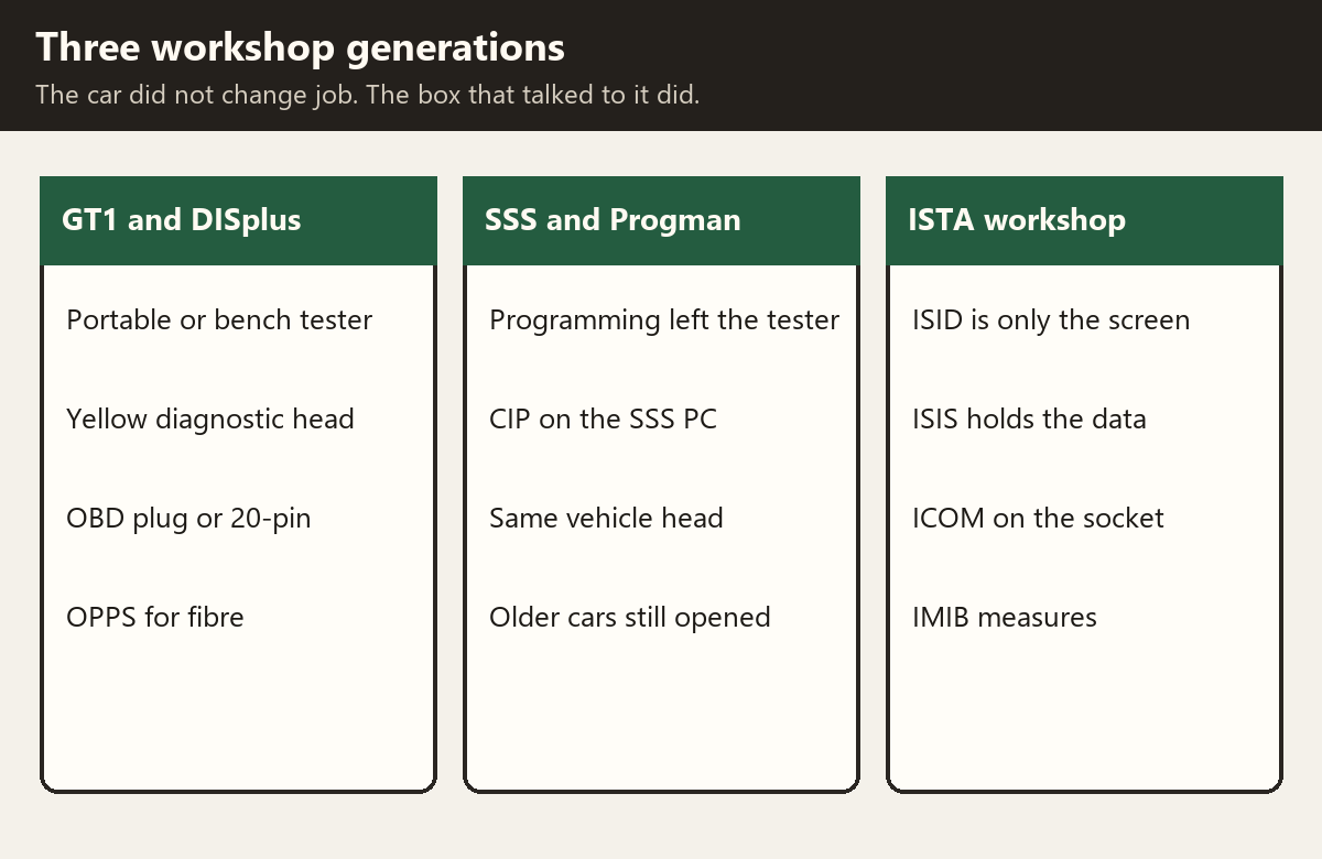
The Group Tester One replaced the MoDiC family as the portable workshop tester. In that generation it is the same class of computer as the DISplus bench unit: a Pentium III, 256 MB of memory and a 20 GB disc, with a DVD drive, a 12.1 inch touch screen and a chip-card reader. The panel weighs about 7.7 lb. Its own battery is good for about two and a half hours and is not a substitute for a supply. The panel also runs from a docking station, a bench supply, or the vehicle battery. The battery is charged in the dock, in about two hours, and the panel is not run with the battery removed, because the battery is the buffer. A forced shutdown, holding the button for about five seconds, is only for a locked machine. It can lose the installed system.
The screen is the control panel. The diagnostic head is a separate piece, and at the introduction of the GT1 the two were joined by cable, not by radio. Three LAN pieces are used, in one order: the uncrossed control-panel adapter, the crossed adapter, and the diagnostic-head cable. The head cable is not plugged in without those adapters. Wireless operation and a measurement kit were planned as later software, not present on the first hard-wired setup. Diagnosis on the GT1 is the same work as on the DISplus. The docking station is the stationary power and network connection. A bench supply is the alternative when no dock was supplied.
The cables that matter for the car are the 16-pin diagnostic cable and the BMW 20-pin cable. Current measurement at the DISplus standard uses a 50 A clip through a size 2 adapter. Which socket a given car actually has is on BMW diagnostic connections. The head itself is the yellow diagnostic head.
The optical head
The E65 and E66 added a second head, the OPPS, because programming and the optical buses are not the yellow head's job. The OPPS of that module is its own computer: a 200 MHz Pentium, 32 MB of flash and RAM, a workshop LAN port, USB, a MOST connection, a byteflight connection and an OBD connection. It does not use a radio link. It covers the model series of that programme, and each unit needs its own network address and a wall socket. Two cable arrangements are described. One runs the OPPS on its own, off the workshop network. The other puts it on the workshop network when a spare socket exists.
The optical work is programming the E65 and E66, and testing the MOST ring and the byteflight star. The fibre itself, and the later ICOM B that took the MOST plug, are on the MOST and fibre-optic networks pages. The OPPS hardware is on OPS and OPPS.
Coding is not programming
A codable module already contains its operating program, plus several sets of operating data. Coding assigns one of those sets: market, gearbox, emissions equipment, the options fitted. It does not write a new program. The ways that assignment was made, depending on the system and the year, are a coding plug pushed into the device, a four-character variant code entered on the DISplus, GT1 or SSS, a selection from the vehicle and key memory, or an automatic run through ZCS coding or CIP. Not every module can be coded.
A programmable module may already hold its operating data and still have no operating program, or it may need both the program and the data brought up to date. Programming loads that program, or updates what was already loaded. It is done from the DISplus, GT1 or SSS in the generation that introduced it. Not every module can be programmed on workshop equipment. A module can also be limited by how many times it has already been programmed, and by its hardware version.

Before either job existed in the workshop, the factory loaded the program or the data as the car moved down the line, and the parts department had to stock every finished variant. Coding and programming exist so a smaller set of hardware can be finished for the car in front of the technician.
CIP, Coding, Individualisation and Programming, is the program that gathered those jobs. It arrived with the E65, from the start of production in November 2001, and the E66 from March 2002, on a DISplus disc. Vehicle and key memory settings, programming, initialisation after programming, and the condition-based service correction sit in that same program. The preconditions and the order are the ones CIP itself demands for that car. They are not optional steps around a failed module.
Programming leaves the diagnostic tester
Progman is the Windows program that runs only on the Software Service Station. It takes over the coding, individualisation and programming that had lived on the DIS disc for the E31, E32, E34, E36, E38, E39, E46, E52 and E53, under the older Unix application, and folds them into CIP. CIP then starts the old Unix path for a car that has not yet been converted, and the Windows path for a newer car. The intention recorded at the end of 2004 was that the E36, E38, E39, E46, E52 and E53 would themselves move into the Windows CIP. Until that conversion, the SSS is starting two different programs, and the choice is the car, not the technician's preference.
Progman can run more than one session. The diagnostic tester is no longer the machine that holds the programming data. The head on the car is still required. SSS and Progman is the equipment page. Classic coding and programming is the earlier ZCS and variant-code path.
The 2008 workshop
From February 2008 the workshop server is ISIS, the Integrated Service Information Server. The generation built on it is the ISID screen, the ICOM head, the ISAP wireless point and the IMIB meter. The applications on that platform are ISTA for diagnosis and programming, ETK for parts, and KSD for labour operations. The rack is sized to keep two existing Software Service Stations as well, so the Progman machines do not leave the building when the new server arrives.
The US rack in that description is a ventilated cabinet, about 700 lb, with two Fujitsu Siemens servers so that one can carry the workshop if the other fails. Each server has two power supplies. An uninterruptible supply of 3000 VA sits under them and will shut the servers down cleanly if the mains fails, rather than letting them die in the middle of a session. A 24-port gigabit switch joins the cabinet to the dealer's own switch. The cabinet is locked, the room is kept between 50 and 77 °F if it is an open rack rather than the ventilated cabinet, and the doors stay shut so the cooling path from the base filter to the rear fans actually works.
The ISID replaces the DISplus and the GT1 as the thing the technician touches. It does not diagnose on its own. Diagnosis needs the ISIS server and an ICOM. Programming needs the same pair. Measurement needs the server and an IMIB. Repair instructions are read on the same screen. The unit of that period is a rugged Windows XP Embedded tablet, about 2.1 kg, with a battery life quoted up to eight hours, a docking station that adds the workshop LAN, USB and a VGA output, and a 12 V lead for use in the car. The GT1 trolley is kept. Only the brackets change, and the new brackets come with the ISID. The wireless side of the building is an ISAP access point on the 2.4 and 5 GHz bands, in 802.11n, administered from Workshop System Management. It is the link for the ISID, the ICOM and the IMIB.
ICOM, and what the lights mean
ICOM A is the head on the 16-pin socket. It is a protocol converter between the tester and the control units, and it is also the path for the IMIB. Power is KL30 from the socket. The head is specified down to 8 V, and it is only stable above that. Below it, an ICOM B hung on the same head is not stable either. The workshop sees it by Ethernet, cable or wireless, at up to 100 Mbit/s.
Four lamps on the A tell you which half has failed. System green means ready, flashing green means it is still booting, red is a fault, and dark means off. LAN green means the cable is up, flashing when there is traffic. WLAN green is an infrastructure network, yellow is an ad-hoc network with the access point offline, and either flashes with traffic. COMM is the vehicle side: K-line, diagnosis CAN, or the vehicle Ethernet.
The A is built so the parts that wear can be changed. Those parts are the OBD module and the fan and connector module. The fan runs when the inside of the head gets hot. The outside limit given for that head is 45 °C. Above it the hardware can shut down in a way that does not recover. The fan inlet has to stay clear.
ICOM B is the MOST adapter. It takes power and data from the A over a USB A-to-B lead, and that lead has to be USB 2.0 high speed if it is not the one supplied. At the introduction of the head, B is not used for diagnosis and is not supported by the service application 2.x. Its own lamps are separate. System off means no power. Yellow means it is initialising. Flashing red means that initialisation failed. Green means ready, flashing green means it is communicating. MOST off means no light in the fibre. Red means light that will not lock. Green means a stable lock. Yellow, red and green together, means an unstable lock.
ICOM C is the adapter from the 16-pin plug to the round 20-pin socket, for cars back to the E30 that have no 16-pin socket. It is powered from terminal 30 on pin 14 of the round socket, and it passes that supply through to the A. A processor in the C converts what the old socket says into the form the A expects. The round socket and the 16-pin socket are not the same pinout. The ICOM family is the page for which adapter fits which car, including the later Next generation, which this 2008 set does not describe.
The meter is part of the test
The IMIB is the measurement box of the same workshop. It measures voltage, current with clips up to 1,800 A, and resistance. Pressure is measured to 2 bar on the box itself and to 100 bar with an external sensor. Temperature uses an external sensor. It also accepts the ignition leads used before it: the static high-voltage lead, the kilovolt clip and the trigger clip. It is a two-channel oscilloscope, and it can stimulate a circuit as well as watch it.
Used inside a test procedure, the value is judged by the procedure and the next step changes because of it. Used on its own, it is a meter. Voltage, current, pressure and resistance show on its own 3.5 inch screen. Temperature and frequency do not. They appear only when ISTA is running the measurement, and in that case the box's own screen stays blank because the result is drawn on the ISID. Registration, language and software updates come from Workshop System Management. The leads from the older measurement box mostly still fit. A USB port on the IMIB was provided for a later diagnostic use. It is not how the 2008 procedures talk to the car. That path is the ICOM.
An ISTA operation
ISTA is the application. The usual mode in the workshop is the dealer workshop mode. Online, the client and the workshop server are on the same LAN or wireless network, and the server has a connection onward to BMW. Data and software updates, and lookups in other BMW systems, travel that link, usually in the background when a function is opened. Offline is a deliberate separation, for example an ISID taken on a road test. Workshop System Management performs the change. When the client can see the server again, it synchronises. The same recovery is used if the server itself has been down.
A third mode does not connect to the car at all. TeleServices receives a file that the car has already sent over the mobile network, either because condition-based service asked for it or because the driver did. The dealer's ISTA, opened from the service-advisor application, starts on the fault memory of that identified car. Only part of ISTA is available. There is no live link back to the vehicle.
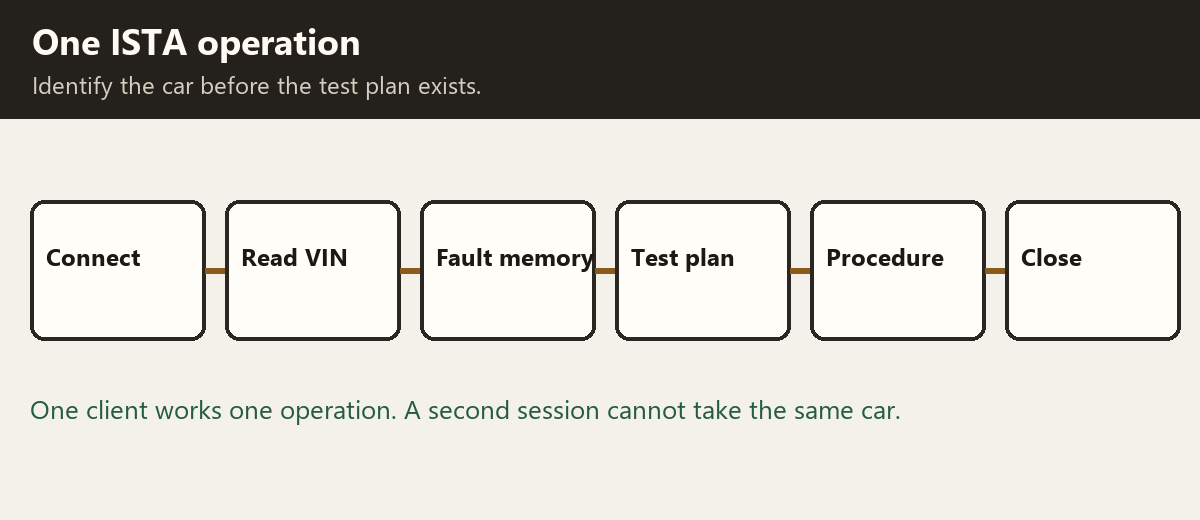
Identification has four starts: an operation that already exists, a VIN typed in, the data read from the connected car, or a selection of basic features. Reading the connected car is the reliable one. Security vehicles cannot be identified by ticking features. They are identified from the VIN. The connection manager lists the ICOM units known to that workshop. The technician picks the one on this car. ISTA then reads the VIN itself.
If that identity already belongs to an open operation, the work continues on it. Otherwise a new operation is created. One ISTA client processes one operation at a time. A second login is not given the same car while communication is open. An operation can be interrupted and resumed, copied, or reopened after it has been closed, in which case the report continues rather than starting again.
The vehicle test is what fills the control-unit tree. The fault memory has to be displayed before a test plan can be opened. The plan is a list of the components and functions the faults point at. A procedure is the localisation and the repair advice for one of those items. Questions inside a procedure are answered in order. The operation ends by finishing it or by interrupting it. The report is the record of what was identified and what was run.
When the workshop asks for help
From February 2005 the path to the technical hotline is PuMA, Product and Measures Management Aftersales. A case is written by the centre, answered by the hotline, and visible only at the centre that sent it. It expires after 90 days. A quality report is a different document. It tells engineering about a product issue and does not expect a hotline answer.
A case is not the first step. The technician is expected to have the training for that system, to have used the bulletins, measures, repair instructions and function descriptions, to have run the test plans and the power and ground checks, and to have spoken to the shop foreman or team leader. The car has to be in the workshop. The tester has to have sent the FASTA data, which is the record that the relevant test modules were actually completed, so the engineer can see that record rather than a description of it. A case is not a warranty authorisation. Warranty questions go to the market team. The foreman, team leader or service manager submits the ordinary case. A technician with the right training can still submit a parts-clearing case.
What did not move
Across all three generations the socket, the head and the program have to match the car. A GT1 with the wrong disc does not become an ISTA session. An ICOM on a 20-pin car still needs the C adapter. An OPPS or an ICOM B in the fibre is a different connection from the diagnostic socket, and it is removed and the ring closed again when the procedure says so. Coding still means selecting data the module already holds. Programming still means loading software. The five-step plan, and the habit of clearing the fault and driving the same conditions again, sit underneath every tester BMW put on the car.