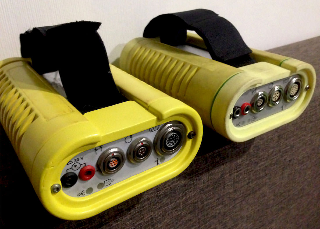
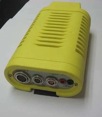
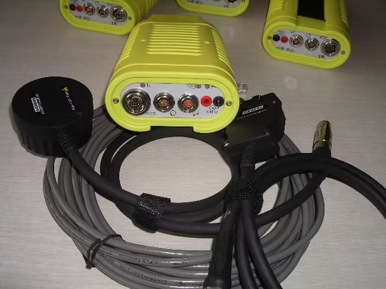
The yellow diagnostic head is a separate interface between the vehicle and a BMW workshop tester. It is often called the DK head or yellow EDIC head. It is not the GT1 display, the DIS diagnostic software, or the later ICOM.
How it fits
BMW's equipment guide lists the diagnostic head with GT1, DISplus and SSS. It describes direct LAN or workshop network connections and wireless options, depending on configuration. The head connects to the vehicle via the correct diagnostic cable, which may be the OBD-style or earlier BMW connector.
MOST distinction
BMW's period guide specifically says not to use this head for programming vehicles with a MOST bus. The optical OPS/OPPS heads served different requirements; confirm the period vehicle and procedure rather than assuming that any head is interchangeable.
Pictures and identification
The BMW equipment guide illustrates the diagnostic and optical heads. An independent historical article shows a yellow head. Identify surviving examples by their markings and connectors as well as colour.
Wireless hardware and board photographs
Some original heads used period wireless hardware. An independent OldBMW.ru case study describes a later Ethernet-to-Wi-Fi bridge and shows the internal boards of both a Siemens unit and a replica. The images document particular examples; identify the board and its connections rather than assuming that all heads share the same layout.
Sources
Curated reference notes. Applicability follows the cited sources; hardware testing by this wiki is not implied.
- BMW Group training: Coding and Programming, equipment and software. BMW of North America service training, Internet Archive copy; illustrated equipment list, workshop networking and coding/programming transition. Source revision ST406, 02 CIP Equipment, especially printed pages 4–7 and 24; accessed 2026-11-10.
- Vintage BMW diagnostic equipment: Sun, MoDiC, DIS and GT1. Independent historical reference with equipment photographs; details are secondary evidence. Source revision Article as accessed; accessed 2026-11-10.
- Wi-Fi modification for BMW GT1/EDIC diagnostic head, OldBMW.ru; first-hand comparison and illustrated board-level case study, source images reproduced with permission.