MOST carries multimedia and control data between vehicle infotainment devices. Optical implementations often connect nodes in a ring. MOST also has physical-layer variants, so use the vehicle wiring information.

Reading the network or diagnostic trace
On an optical ring a failed node, absent power or interrupted fibre can affect multiple devices. Investigate the ring continuity and node power before assigning an application fault to an individual module.
See Diagnostic ports before and after EOBD and the vehicle diagnostics protocol guide.
Sources: ACTIA IME overview and standard or technical reference.
Detailed reference
MOST, Media Oriented Systems Transport, is the optical ring used for infotainment. It carries audio, video, navigation pictures and the control messages that start and stop those streams. It is not the bus a serial logger uses for engine speed or fuelling. Those sessions are on the diagnostic communication protocols page. What changes between a BMW and an Audi is not the fibre. It is which control unit runs the ring, how a break is found, and whether the workshop tester joins the ring or stays on the diagnostic CAN.
The account below follows the MOST Cooperation book based on specification 3.0 E2 of July 2010, BMW's E65/E66 training module of 2002, Audi's self-study descriptions of the A8 and of the Modular Infotainment System, and the ISTA/P instructions for the ICOM B. A ring order or a part number from one of those documents belongs to the cars that document covers.
MOST is one optical network on the car. The E65 also has byteflight, a separate fibre in a star, used by the restraint system. Mercedes had an earlier optical ring, D2B, on the cars that predate MOST. Those three sit together on the fibre-optic networks page. CAN, LIN and automotive Ethernet are linked from there because they are copper networks, not more fibre.
Where the bus came from
A 2015 survey of vehicle fibre names the first partners as Audi, BMW and DaimlerChrysler, with Harman/Becker and Oasis Silicon Systems. The same paper separates three generations. MOST25 uses a 512-bit frame on plastic fibre. MOST50 doubles the frame to 1,024 bits and, in that account, was carried mainly as an electrical signal. MOST150 returns to fibre with a 3,072-bit frame. The MOST book, written against the 2010 specification, is more precise about the rates and is the source of the table below.
| MOST25 | MOST50 | MOST150 | |
|---|---|---|---|
| Frame | 512 bits | 1,024 bits | 3,072 bits |
| Frame rate | 44.1 kHz | 48 kHz | 48 kHz |
| Stream, maximum | 21.168 Mbit/s | 44.928 Mbit/s | 142.848 Mbit/s |
| Packet data, maximum | 10.841 Mbit/s | 44.544 Mbit/s | 142.848 Mbit/s |
| Control, gross | 405.84 kbit/s | up to 810.62 kbit/s | up to 1,130 kbit/s |
| Physical layer in the book | Optical | Optical, and an electrical layer was also specified | Optical, 147.56 Mbit/s at 48 kHz |
The 22.58 Mbit/s figure for MOST25 is the arithmetic in that book: 512 bits, sent 44,100 times a second. BMW's E65 module, written earlier, teaches the same bus as about 22.5 Mbit/s and divides each message into control data, asynchronous data such as a navigation arrow, and synchronous data such as audio and video. It gives the control channel as about 700 kbit/s, around 2,700 messages a second, and a shared pool of 60 bytes whose split between synchronous and asynchronous data can change. The 700 kbit/s and the book's 405.84 kbit/s are not the same accounting. The module is describing the control slot as BMW taught it in 2002. The table is the later specification summary. Neither number is a sample rate for an engine channel.
The fibre and one hop
The optical layer in the MOST book is polymethyl methacrylate plastic fibre, a polymer optical fibre, with a 1 mm core. The transmitter is a light-emitting diode in the red wavelength range. The receiver is a silicon photodiode. BMW's E65 module states the wavelength as 650 nm, which is that red light, and says the fibre is coded green in the E65 wiring diagram while repair cables are black. Each control unit has a transmitter and a receiver. The fibre optic receiver turns light into an electrical signal for the network interface controller. The controller's transmit signal is turned back into light by the fibre optic transmitter. Together those two parts are the fibre optic transceiver, the FOT.
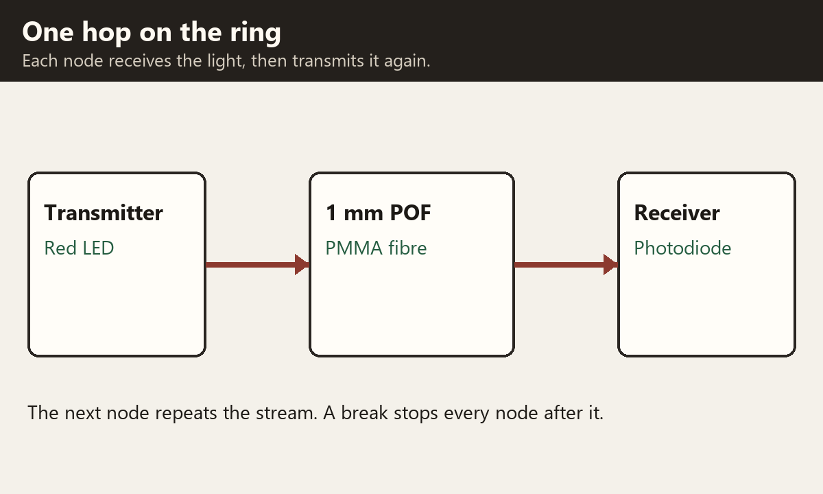
The ring is a series of those hops. Data travels in one direction. Each node passes the stream to the next until it returns to the node that sent it. The book limits a ring to 64 nodes. The timing master always takes node-position address 0x400. Each following node is 0x400 plus its position, so the last address in a full ring is 0x043F. Until the timing master has assigned an address, an uninitialised node holds 0xFFFF. On the E65, the control display is the system master and the power master: it wakes the bus and it shuts it down. The audio system controller is the network master. It initialises the network, compares the nodes it finds with the coded configuration, stores the network fault memory, and, as connection master, allocates the channels. Audi's A8 self-study splits the same jobs differently. The front information display and operating unit, J523, is the system manager. The data-bus diagnostic interface, J533, is the diagnosis manager.
A node that is present but not running normally does not have to break the ring. The network interface controller has an integrated bypass. The book says the bypass is closed, or stays closed, when the controller is not in normal operation, including during an error or while the device is starting. In that state it passes the incoming stream on to its transmitter with almost no delay, and without regenerating it. That is an electrical path inside the controller. It is not a piece of fibre a technician plugs in.
Handling the fibre
The light is lost in ordinary workshop damage, and the two manufacturers publish different limits, so they are not collapsed into one rule.
Audi's optical-bus self-study treats attenuation as the ratio of transmitted power to received power, in decibels, and says a 3 dB loss halves the light. Only the loss between two control units matters, because each control unit transmits again. The causes it lists are a bend tight enough to kink the core, cladding damage, a scratched or dirty end face, end faces that are offset or angled, a gap because the connector is not latched, and a ferrule that was crimped badly. It forbids soldering, hot bonding, welding, gluing or twisting two fibres, or twisting a fibre with a copper wire. Protective caps stay on until the moment of connection. An anti-kink sleeve in that programme keeps the radius at 25 mm or more. A kink tighter than a 5 mm radius obscures the core, and that fibre is replaced.
BMW's E65 module gives a minimum bend radius of 50 mm for the fault "optical waveguide communication fault". It also names a dirty or unseated connector, a diode whose light output or sensitivity is low, and a voltage dip while a module powers up. The repair note in that module gives AMP butt connector 1355734-1. That part number is the one in the E65 procedure. It is not a claim that every MOST car uses it.
Loop devices
Removing a node opens the ring, because the light has nowhere to go. A fibre loop is a short piece of the same fibre that joins the incoming fibre to the outgoing fibre, so the light skips the missing node. The internal bypass described above cannot do that job: it lives inside the controller that has been unplugged.

On an Audi, Ross-Tech describes part 4E0 973 802 as a fibre loop fitted in place of each component in turn, to see whether that component is what opened the ring. The optical-bus diagnosis in VCDS reports which modules are electrically present and between which two the light has stopped. If that result is inconclusive, the diagnostic type is changed from standard to 3 dB attenuation: the modules transmit at lower power, which shows up a fibre that still passes full power but has too much loss. Audi's own self-study describes the same half-power test. The LEDs are run at 3 dB down, and a receiver that then reports an optical problem marks the weak hop.
MOST150 does not use the MOST25 substitute tool. Audi's Modular Infotainment description says the fibre, the optical connectors and the electrical connectors stay as they were for MOST25, but the transmitter and receiver units changed. An optical fault on that bus is traced with the optical substitute control unit VAS 6778, because of those different transceivers. The ring-break test itself is started at address 5F.
On a BMW, the E65 procedure is the same shape of test with different tools. Read the fault memories in ring order. The fault lies between the first module that stored it and the module before that one. Confirm by clearing the fault, lowering the light output of the upstream module, and reading the ring again. If the same module stores it first, inspect the connector and the fibre, then fit a bypass waveguide in place of one module and then the other. The OPPS tester is the tool named for that job in the 2002 module. Later, ISTA/P uses the ICOM B in the MOST direct-access port and tells the operator, when the program asks, to remove the ICOM from the ring and close the ring with the original flash plug, which it also calls the bridge. Leaving the ICOM in the ring after that request can store fault codes and register MOST modules incorrectly.
How BMW built it
The E65 and E66 training module is the detailed BMW account. With full equipment, the light leaves the control display and runs, in this order, to the CD changer, the antenna tuner, the hi-fi amplifier, the speech-processing module, navigation, the multimedia changer, the telephone, the audio system controller, the instrument cluster, and back to the control display. The module warns that the wiring diagram of that period shows the sequence incorrectly, and that this order is the direction of the light. Component locations in the same module put the control display, CD changer, audio system controller, instrument cluster and the OPPS connector in the dashboard, and the amplifier, speech module, navigation, multimedia changer and telephone at the rear left of the luggage compartment. The antenna tuner is in the left C-pillar. A car without one of those options does not grow an empty seat in the ring. The order is the full-equipment order.
If the ring is open, messages cannot cross the gap. Diagnosis then reaches only the instrument cluster and the control display, because those two are also on the K-CAN. The control display is shown twice in DIS and GT1: once as the display, and once as the gateway between MOST and K-CAN. Faults are stored against the function they belong to. The module lists optical-waveguide communication fault 111, a module that does not switch its light off, network wake-up unsuccessful E18D, and ring-fault diagnosis carried out E190. E190 is not a failed part. It is the record that the ring-fault routine ran, and it carries the relative node position.
Sleep is optical. When the network is asked to sleep, the control display switches its light off. Modules downstream take the absence of light as the instruction to switch their own light off and sleep. A module that keeps transmitting leaves every module after it awake. The module says the rest of the car then cannot sleep, and the battery discharges. The fault is stored in the modules downstream of the one that left its light on, so the failed module is the one before the first stored fault.
The workshop interface changed with the tester. The 2002 module uses the OPPS, the optical testing and programming system, whose connector is in the dashboard on that car. ISTA/P, which does not support OPS or OPPS, uses the ICOM. ICOM A is the OBD interface. ICOM B is the external MOST interface: a USB A-to-B cable from ICOM A, power taken from ICOM A over that cable, and a MOST connector into the vehicle's MOST direct-access port. ICOM A still has to be on the OBD socket as well. The ISTA/P model table of August 2008 marks a MOST direct-access port, and therefore ICOM A with ICOM B, on the E81, E82, E87, E88, E90, E91, E92, E93, E60, E61, E63, E64, E65, E66, E70 and E71. The same table leaves the F01, F02, E83, E85 and E86 without that MOST column. The port is a feature of the car, not of owning an ICOM B. BMW diagnostic connections and the ICOM family are the pages for which head talks to which socket.
How Audi built it
Audi's A8 self-study of 2003 puts the diagnosis of the MOST ring on the data-bus diagnostic interface and the diagnostic CAN. The tester, a VAS 5051 or VAS 5052 in that programme, plugs into the ordinary diagnostic connection. It does not plug into the fibre. J533 collects the diagnostic data from the ring and passes it to the tester. The system manager, J523, controls system status, sends MOST messages and manages the transmission capacity.
Because a broken fibre stops the messages that would have reported the break, Audi runs a separate electrical wire to every MOST control unit, tied at one central connection. That wire is only for ring-fault diagnosis. The self-study says it is not a path for the audio or the pictures. After the test starts, each control unit reports two things on that wire: whether it is electrically alive, and whether its photodiode is receiving light from the previous control unit. The diagnosis manager can then say which units have no supply, and between which two the light has stopped. The consequences of a break, in that programme, are no audio and no video, no control from the multimedia operating unit, and a fault in the diagnosis manager for a break in the optical data bus.
Sleep on this Audi is also optical, from the other end of the same idea. In sleep there is no data exchange. The units sit in standby until an optical start pulse from the system manager. They enter sleep only when every MOST unit has declared itself ready and nothing else on the bus is requesting them.
The Modular Infotainment System is where Audi first uses MOST150, described there as six times the MOST25 bus. The development changed the transmitter and receiver units. The optical connectors, the fibre and the electrical connectors of the control units stayed as they were. Video from the TV tuner or the DVD changer now travels on the optical bus, and the separate composite-video connection used with MOST25 is no longer fitted. At most five control units sit on that MOST bus: the information-electronics control unit J794, the digital sound-package control unit J525, the TV tuner R78, the DVD changer R161, and the instrument-panel control unit J285. J794 is both system manager and diagnosis manager, a job that had belonged to J533. Its diagnostic address on every MIB version in that description is 5F, electronic information systems. The ring-break procedure is unchanged, and it is started at address 5F. The substitute tool for an optical fault is VAS 6778.
A later Audi technical description of the A8 repeats the same split. MOST150 is six times MOST25. The fibre optic transmitters were adapted. Connectors, fibre and the electrical connectors of the control units match MOST25. J794 is system manager and diagnostic manager. The control units are still tied together by the electronic ring-break diagnosis line, and that line is used only after MOST communication has been lost. It is not how the modules exchange their data. Address word 5F on the VAS scan tool is again the way in, and VAS 6778 is again the tool when the fault is optical.
The same ring, two workshop methods
| BMW, from the E65 module and ISTA/P | Audi, from the A8 and MIB descriptions | |
|---|---|---|
| What the fibre carries | Audio, video, navigation graphics, control. About 22.5 Mbit/s in the 2002 module. | The same three kinds of data. MOST25 on the earlier ring. MOST150 from MIB, with video on the fibre. |
| Who runs the ring | Control display is system and power master. Audio system controller is network master, connection master and holder of the network fault memory. | J523 is system manager on the A8 of that self-study. J533 is diagnosis manager. On MIB, J794 does both. |
| How the tester connects | The optical head joins the ring. OPPS in 2002. Later, ICOM B on the MOST direct-access port, with ICOM A on the OBD socket. Only on cars fitted with that port. | The tester stays on the diagnostic connection. J533, or J794 on MIB, is the diagnosis manager. Address 5F on MIB. |
| How a break is located | Fault memories read in ring order, then a lowered light output, then a bypass waveguide. K-CAN still reaches the cluster and the control display. | A separate electrical diagnosis wire. Each node reports electrical life and whether light arrived. Then the 3 dB test for a weak fibre. |
| The loop | Bypass optical waveguide in the E65 procedure. The original flash plug, also called the bridge, closes the ring when ICOM B is removed. | Fibre loop 4E0 973 802 in place of a suspect module. VAS 6778 when the bus is MOST150, because the transceivers differ. |
| Fibre rules in the source | 50 mm minimum bend in the E65 fault description. Repair butt connector 1355734-1. | 25 mm with the anti-kink sleeve. A kink inside 5 mm replaces the fibre. No heat, glue or twist repairs. Caps stay on. |
A BMW optical head on an Audi diagnostic socket does not become an ICOM B, and an Audi address-5F test does not open a BMW MOST port that the car does not have. The speed generation matters for the substitute tool: Audi says the MOST150 transceiver is not the MOST25 transceiver, which is why VAS 6778 exists. The fibre and the connector body, on that Audi account, did not change with the speed.
Sources
- MOST book, second edition. MOST Cooperation. Based on MOST Specification 3.0 E2, July 2010. Frame table, 1 mm PMMA fibre, red LED, silicon photodiode, 64-node ring, timing-master address 0x400, and the network-interface bypass. Accessed 2026-11-12.
- Fibre optics transmission for vehicle applications. Krzysztof Perlicki, Measurement Automation Monitoring, 2015. Founding companies, 650 nm, and the MOST25, MOST50 and MOST150 frame sizes. Accessed 2026-11-12.
- MOST Bus Diagnosis. BMW Group technical training, E65/E66, initial print 03/02, revision 08/02. Ring order, masters, 650 nm, 22.5 Mbit/s, fault codes, bend radius, bypass waveguide and the OPPS. Accessed 2026-11-12.
- Integrated Communication Optical Module. BMW technical training. ICOM A, and ICOM B as the external MOST interface supplied over USB from ICOM A. Accessed 2026-11-12.
- ISTA/P programming user documentation. BMW. MOST direct-access port, the model-series table, and closing the ring with the original flash plug. Accessed 2026-11-12.
- Self-study programme, optical bus. Audi/Volkswagen SSP 286. Attenuation, fibre-handling rules, J523 and J533, the diagnosis wire, and the 3 dB test. Accessed 2026-11-12.
- Audi Modular Infotainment System. Self-study, VW USA copy 994618. MOST150, unchanged connectors and fibre, changed transceivers, J794, address 5F and VAS 6778. Accessed 2026-11-12.
- Audi A8 MOST150 description. NHTSA copy MC-10144683. MOST150 against MOST25, the diagnosis line, address 5F and VAS 6778. Accessed 2026-11-12.
- Optical bus diagnostics. Ross-Tech. Fibre loop 4E0 973 802 and the 3 dB attenuation test in VCDS. Accessed 2026-11-12.