ECUMASTER supplies motorsport displays, engine management and data-acquisition components. Its ADU is a combined driver display and logger; the separate EDL-1 records data from compatible EMU ECUs. Some EMU PRO controllers also record to USB. Available channels depend on the exact device, connected sensors, ECU stream and configuration. Manufacturer photographs are available on the linked product pages.
Data-log analysis software: Data Master
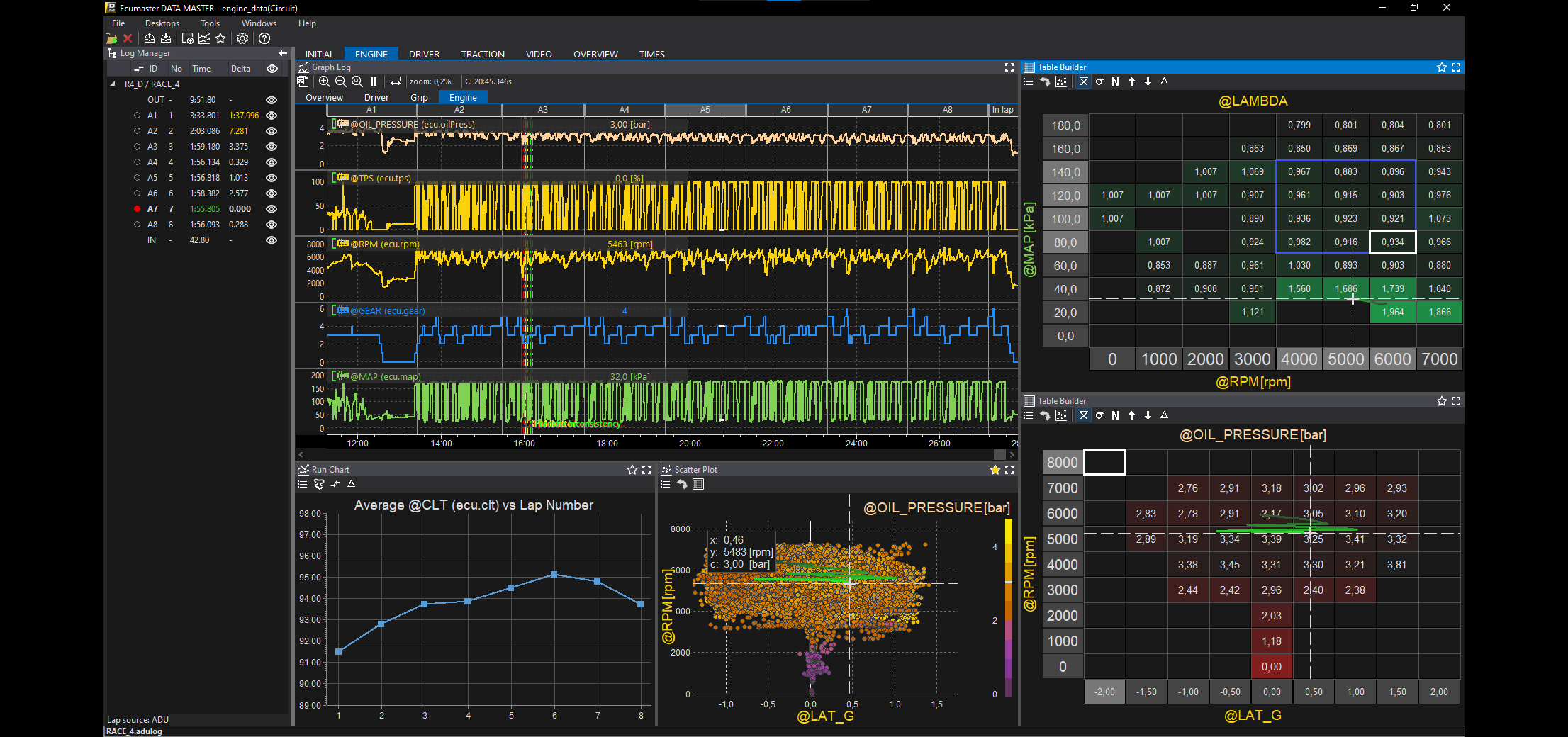
ECUMASTER Data Master is the manufacturer's free PC analysis application for recordings from ADU, PMU, EMU PRO, EMU Black, EMU Classic and EDL-1 devices. The Data Master product page supplies the installer, manual, sample data and changelog; check the listed release and device software version before installation.
Load a recording to plot channels against time or distance, compare laps and examine a reference track by segment. Data Master supports user-defined maths and channel aliases, user-defined log splits, and video analysis with automatic synchronisation. Its graph view can export CSV; export settings and interpolation affect the resulting samples. The manufacturer also documents automated CSV export.
For an ADU, copy a recording from its USB drive and open it in Data Master for detailed analysis. The ADU USB-logging guide also describes the ADU Client's basic graph and export functions. ADU Client is the device configuration tool; Data Master is the dedicated analysis tool. Available channels depend on the logger configuration and connected equipment.
Step-by-step: download and analyse a log in Data Master
This example uses the ADU USB workflow and Data Master 2026.3; controls can vary by release. ECUMASTER also lists EMU, PMU and EDL-1 recordings as supported. The recorded channels, GPS laps and video depend on the device and its configuration.
- Install the software: download Data Master and its manual from ECUMASTER’s Data Master page. Confirm the installed version and compatible device; Data Master is the analysis application, while ADU Client configures and can download from the dash.
- Get the ADU log: after stopping the recording, copy the .ADULOG session from the ADU USB drive to the computer. Alternatively, after moving the USB drive to the PC, open ADU Client and choose Devices → Receive Logs (Shift+F4) to view the stored logs. The manufacturer documents both methods. For an EDL-1, transfer recordings using its SD card: its manual says direct PC and Bluetooth transfer are not supported. ADU logging and retrieval guide; EDL-1 manual.
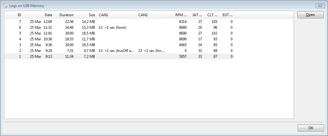
ADU Client: the Logs on USB Memory dialog after choosing Devices → Receive Logs. This is the ADU Client retrieval screen, separate from Data Master. Example from the ADU manual, document 120.2.4; layout may vary by release. Image: ECUMASTER, reproduced with permission; manufacturer ADU manual, page 171. - Open the session: start Data Master and create or open a project. Choose File → Open log (Ctrl+O), then select the saved recording. If no session is available yet, the product page offers sample data. Data Master manual, sections 2–4.
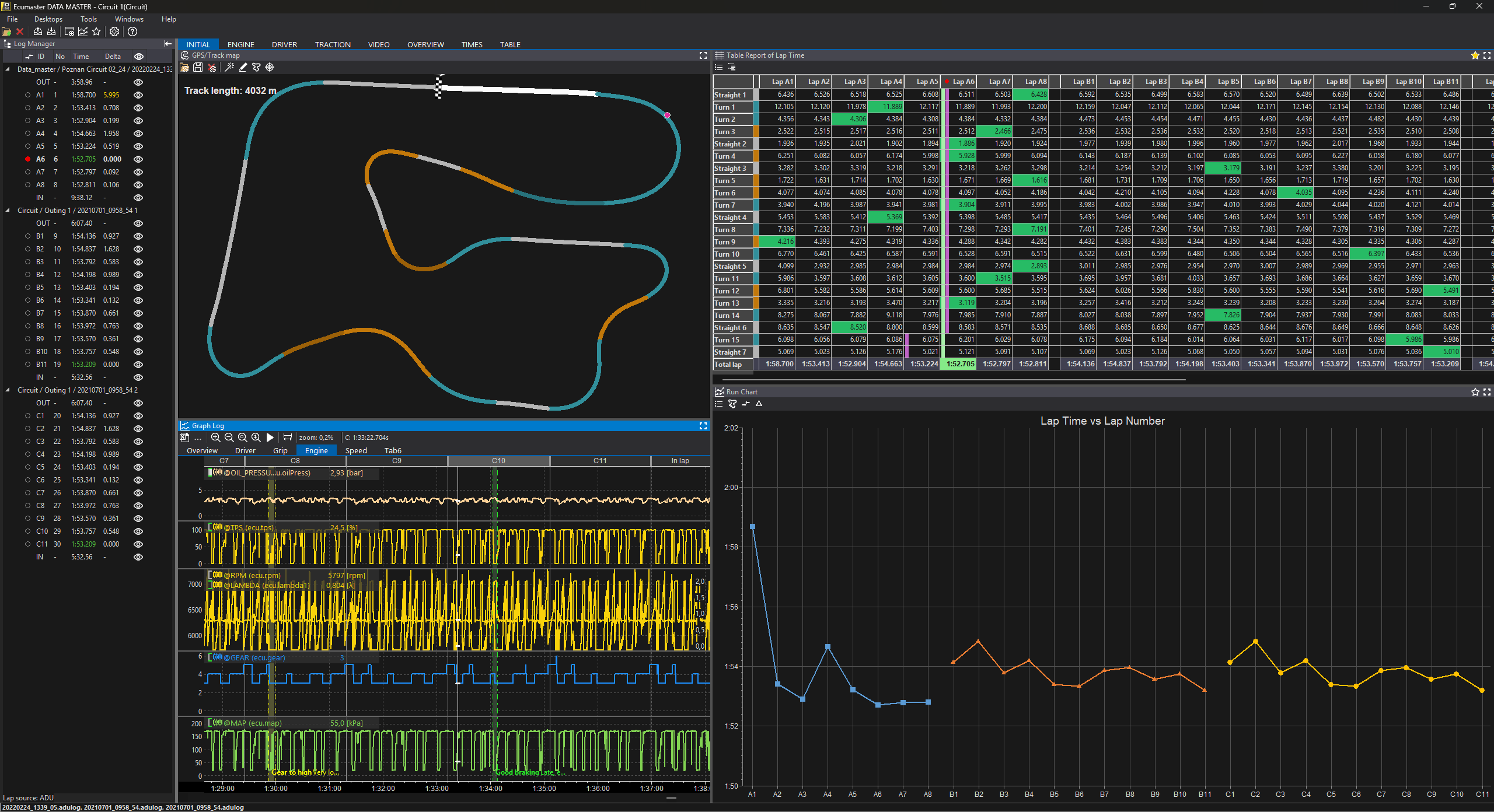
Data Master desktop after a log has been loaded: the File menu is at top left and the Log Manager, graph and track views are visible. Example from the 2026.3 manual; screen layout and available data vary. Image: ECUMASTER, reproduced with permission; manufacturer manual, page 7. - Plot channels: use the Graph Log panel to show logged channels against time or distance; add or change channels and search by name, for example speed, engine speed or throttle. Check the units and that the chosen channels contain data. Use time for a stationary or dyno log where a lap or distance is not available.
- Compare laps: in Log Manager, select a base lap and a comparison lap using the circles next to their names: red is the base and white the comparison. In Graph Log, press T to switch the comparison between time and distance. If the recording lacks usable lap markers, use Tools → Lap Editor (F5) to review the split. GPS and a suitable track reference are needed for track-position analysis.

Data Master Log Manager: red marks the base lap and white the comparison lap. Example from the 2026.3 manual. Image: ECUMASTER, reproduced with permission; manufacturer manual, page 11. - Review and export: inspect the same section in the graph and GPS/track view when GPS was recorded; add the corresponding video if available and check synchronisation. Graph Log offers Export to CSV, with settings that affect output sample frequency and interpolation. Save the project and retain the original log. Data Master manual, Log Manager, Lap Editor and Graph Log sections.
Individual datalogger models
- ECUMASTER ADU5 — five-inch dash logger, standard 35-position connector.
- ECUMASTER ADU7 — seven-inch dash logger, standard connector.
- ECUMASTER ADU5 Autosport — five-inch dash logger, 37-position AS connector.
- ECUMASTER ADU7 Autosport — seven-inch dash logger, 37-position AS connector.
- ECUMASTER EDL-1 — standalone serial ECU data logger.
ADU5, ADU7 and ADU7 Autosport

The Advanced Display Unit (ADU) combines a configurable colour display, warnings, shift LEDs, inputs and logging. ADU5 and ADU7 have 5-inch and 7-inch screens respectively; ADU7 Autosport uses a different connector arrangement. Check the physical revision, connector and enclosure rating for the exact unit. Channels can be recorded to an external USB flash drive at up to 500 Hz, with Data Master for analysis. That maximum does not mean that a connected ECU sends all channels at 500 Hz.
The ADU product page lists eight analogue inputs, eight digital inputs, two CAN 2.0 interfaces and RS232. ECU templates and configurable CAN streams allow integration with a range of ECUs; verify the exact protocol, bit rate, wiring, channels and available sample rates. Consult the ADU manual and relevant application note before connecting a vehicle.
Configure which channels are recorded and at what rate: the USB logging guide describes conditional logging profiles and per-channel frequencies. Confirm that the drive is recognised and test the file before a session.
EDL-1 ECU data logger
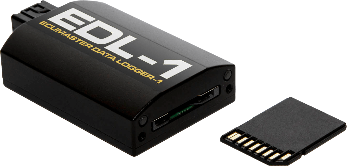
The EDL-1 is a separate logger for compatible EMU and EMU BLACK systems. ECUMASTER describes serial recording of over 200 channels at 25 Hz onto supported FAT32 SDHC cards, with a battery-backed clock and Bluetooth. The exact ECU, firmware, card and wiring should be checked against the product page and manual. It does not replace the ADU's display, GPS and input functions.
EMU ECU recording
ECUMASTER's ECU comparison lists real-time PC logging for EMU CLASSIC, EMU BLACK and EMU PRO, and separate external logging through EDL-1 for CLASSIC/BLACK or a USB flash drive for PRO. The page lists 20 Hz for CLASSIC, 25 Hz for BLACK and up to 500 Hz for PRO. These are product-specific maximums, not proof that every source channel has the same update rate. ECU hardware is primarily engine management; it should not be confused with a standalone dashboard logger.
GPS, analysis and live display
The GPS to CAN module supplies GPS position and motion data to a compatible ADU for lap timing and track analysis. ECUMASTER lists 20 Hz on its original product page; its 2025–2026 catalogue lists 25 Hz for GPS to CAN V2. Match the module version, antenna and firmware to the installation; the ADU manual specifies its supported GPS interface.
Data Master analyses recordings from supported ECUMASTER devices and provides mathematical channels, track-segment analysis and synchronised video. Compare laps and engine operating conditions consistently and verify sensor scaling before drawing conclusions.
eDash displays compatible ECU data live over Bluetooth on a phone or tablet, using the appropriate EDL-1, BT CAN or Bluetooth interface. Compatibility and on-screen control depend on ECU version, interface and firmware; the manufacturer publishes a compatibility table. Bluetooth local display is not, by itself, evidence of remote internet telemetry. An additional supported transmission and receiving system would be required for off-site reporting.
Pinouts and cabling
These are device-specific cavity numbers, transcribed from ECUMASTER documents linked below. Check the exact product and physical connector against the manufacturer's connector-face drawing before wiring. Check which component and view each diagram depicts. Isolate power before continuity checks. Do not infer pin assignments from wire colours, and confirm the intended supply, current limits, CAN network and sensor requirements in the applicable manual.
ADU5 and ADU7 — standard 35-position connector
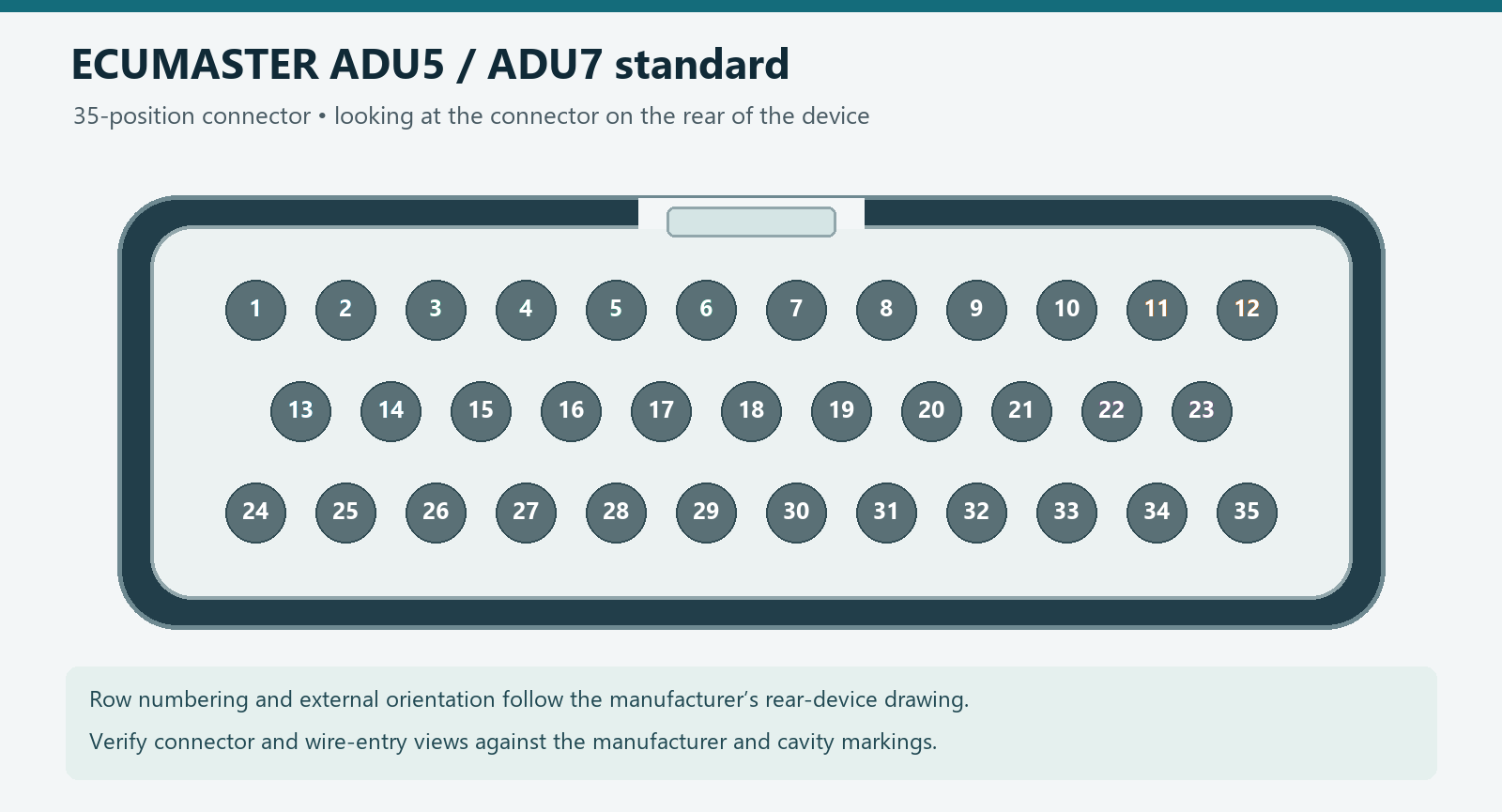
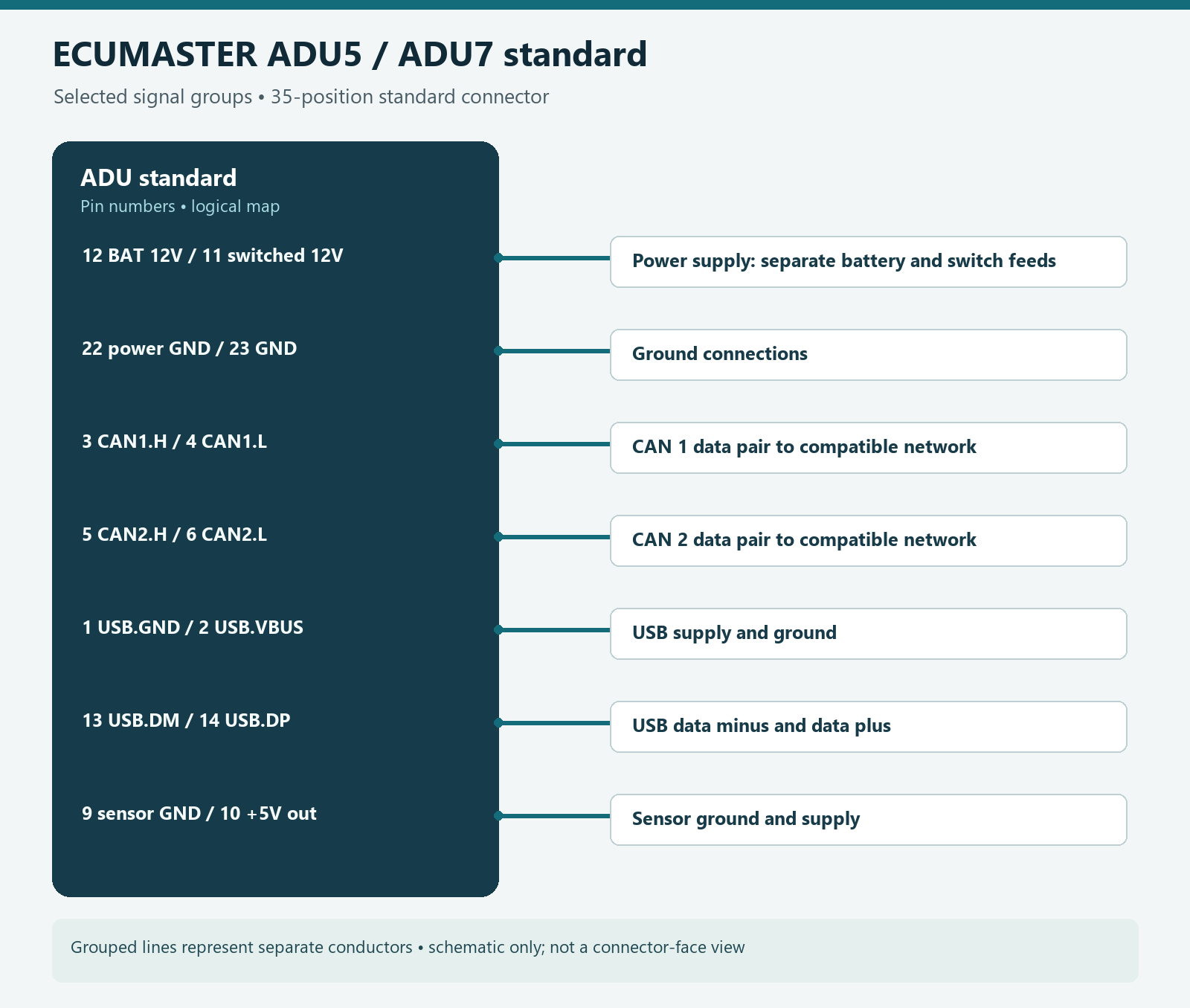
This table is for the standard ADU drawing, not ADU7 Autosport. The manufacturer lists a 35-position AMP automotive connector for the standard model. Pin numbers follow ECUMASTER’s ADU pinout drawing; use its face diagram to orient the connector. USB.DM and USB.DP are USB data minus and plus.
| Pin | Function |
|---|---|
| 1 | USB.GND |
| 2 | USB.VBUS |
| 3 | CAN1.H |
| 4 | CAN1.L |
| 5 | CAN2.H |
| 6 | CAN2.L |
| 7 | RS232.RXD |
| 8 | RS232.TXD |
| 9 | Sensor ground |
| 10 | +5V output |
| 11 | Switched 12V |
| 12 | Battery 12V |
| 13 | USB.DM |
| 14 | USB.DP |
| 15 | Analog in A5 |
| 16 | Analog in A3 |
| 17 | Analog in A1 |
| 18 | Frequency/digital in D8 |
| 19 | Frequency/digital in D6 |
| 20 | Frequency/digital in D4 |
| 21 | Frequency/digital in D2 |
| 22 | Power ground |
| 23 | Ground |
| 24 | Analog in A8 |
| 25 | Analog in A7 |
| 26 | Analog in A6 |
| 27 | Analog in A4 |
| 28 | Analog in A2 |
| 29 | Analog output |
| 30 | Frequency/digital in D7 |
| 31 | Frequency/digital in D5 |
| 32 | Frequency/digital in D3 |
| 33 | Frequency/digital in D1 |
| 34 | Aux 1 |
| 35 | Aux 2 |
ADU7 Autosport — 37-position connector
The Autosport model uses different pin numbers and a different connector; do not use the 35-position table above. The ADU AS pinout drawing identifies mating connector Deutsch AS614-35SN and shows its orientation. Confirm the hardware revision and mating connector before wiring.
| Pin | Function |
|---|---|
| 1 | Battery 12V |
| 2 | Frequency/digital in D1 |
| 3 | Frequency/digital in D2 |
| 4 | +5V output |
| 5 | +5V output |
| 6 | AUX2 |
| 7 | Power ground |
| 8 | AUX1 |
| 9 | Analog in A2 |
| 10 | Analog in A1 |
| 11 | Analog in A3 |
| 12 | Analog in A5 |
| 13 | Analog in A7 |
| 14 | USB.VBUS |
| 15 | CAN1.H |
| 16 | CAN2.H |
| 17 | CAN2.L |
| 18 | Analog output |
| 19 | RS232.RXD |
| 20 | Frequency/digital in D3 |
| 21 | Frequency/digital in D4 |
| 22 | Frequency/digital in D5 |
| 23 | Frequency/digital in D7 |
| 24 | Analog in A4 |
| 25 | Analog in A6 |
| 26 | Analog in A8 |
| 27 | USB.DM |
| 28 | USB.DP |
| 29 | CAN1.L |
| 30 | RS232.TXD |
| 31 | Switched 12V |
| 32 | Frequency/digital in D6 |
| 33 | Frequency/digital in D8 |
| 34 | Sensor ground |
| 35 | USB.GND |
| 36 | Sensor ground |
| 37 | Ground |
EDL-1 logger — four-position connector
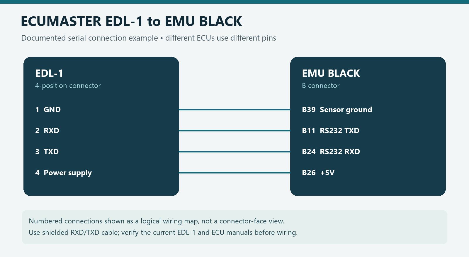
The EDL-1 manual, installation section identifies a Molex 34793-0040 connector and calls for a 5–20 V supply. The manual's illustration views the connector face, with pin 1 on the left and pin 4 on the right. Use shielded cable for RXD and TXD.
| Pin | Function |
|---|---|
| 1 | Ground |
| 2 | RXD |
| 3 | TXD |
| 4 | Power supply |
For the manual's EMU Black example, EDL-1 pins 1, 2, 3 and 4 connect respectively to EMU Black B39 sensor ground, B11 RS232 TXD, B24 RS232 RXD and B26 +5 V. For its EMU Classic example, those EDL-1 pins connect respectively to Classic pins 4 ground, 2 TXD, 1 RXD and 5 +5 V. These examples apply to the stated ECU connectors only; check the current ECU and logger manuals before construction. ECUMASTER also describes a separate 12 V and chassis-ground power option.
System cabling
- For an ADU, use the exact ECU's supported CAN or serial protocol and configure the ADU channel decoding and bus speed. A matching connector does not establish compatible ECU data.
- Wire USB to the designated VBUS, ground, data-minus and data-plus pins; the standard ADU and ADU AS assignments differ. The manufacturer diagrams show the USB-A receptacle view.
- GPS-to-CAN, ECU and other CAN modules require the correct CAN high/low pair, appropriate power and the configuration for the intended bus. Consult the device-specific instructions for termination and supply limits rather than assuming every device supplies termination or power.
- Choose the sensor ground, reference supply and analogue/digital input named in the right diagram, then configure input type, scaling and logging rates in the software. AUX outputs require the documented electrical limits and loads; do not assume they are sensor supplies.
Selection and installation
- Choose the channels, intended sample rates and whether an in-car display, local storage, GPS or a remote live feed is needed. Check the complete kit and software versions.
- Confirm compatible ECU protocol, wiring and CAN configuration. A CAN connection does not guarantee a specific channel is transmitted.
- Verify sensor calibration, storage, timestamps and a short test recording before relying on data. Follow manufacturer mounting, power and wiring instructions.
See the in-car datalogging and telematics overview and ADU and Bosch DDU 11 comparison. Product photographs are credited to ECUMASTER and reproduced with permission; specifications are linked above.