The I-bus is the single-wire information bus on the BMWs that still keep the radio, the CD changer, navigation and the telephone on copper. The audio keys on the steering wheel use the same wire. The frame is the K-bus frame: 9600 bit/s, eight data bits, even parity, one stop bit, with the wire sitting at battery voltage until the module that is talking pulls it to ground. Engine data stays on CAN. From the E65, the pictures and the audio streams move onto MOST. LIN is the later single-wire sub-bus for seats, wipers and the same sort of local job, and it has its own frame.
The button, screen and changer codes below were captured on one car: an E39 built in July 2000, with the Mk II navigation system. A code from that log is a code from that car. The same byte is used for a different module in some later lists, and those clashes are marked where a frame in this log actually decides the question.
A workshop tester programmes the engine on the diagnostic connection. Which socket that is, and which head talks to it, is on the BMW diagnostic connections page. The entertainment frames are on the I-bus itself, at the radio, the changer or the navigation unit.
The wire
One conductor does both directions, so only one module talks at a time. The wire is pulled up to battery voltage, about 12 V, and a talker sends a dominant bit by pulling it to ground. Idle is the high, pulled-up state. The start bit is the low. It is the ISO 9141 K-line family, run at 9600 bit/s. A diagnostic K-line session uses 10.4 kbit/s, and a logger left at that rate will not stay in step with these bytes.
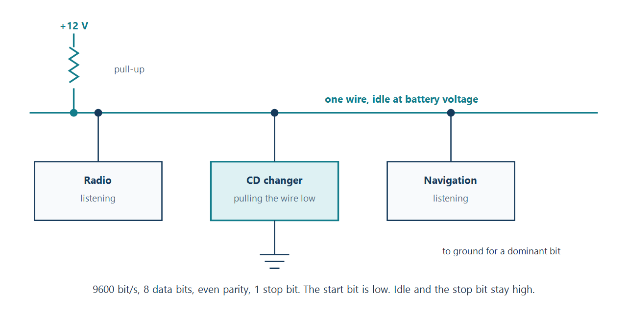
On the E39 the wire was found at the CD changer connector in the boot, at the navigation CD connector, and at the telephone connector in the centre console, coloured white/red/yellow. On an E46 the same colour is the K-bus in the CD-changer plug an Arduino library calls X18180, in the boot on the driver's side, with red/green for battery and brown for ground. That bus is not on the 16-pin diagnostic socket. A junction block above the fuse box is the other place that library shows, and there every white/red/yellow wire is the K-bus. The wiring diagram for the chassis decides the colour when a car differs.
Any module may start a frame once the wire is idle. The frame carries no priority field, so two modules that start together overwrite each other and both frames are lost. The E39 capture did not measure the idle gap. The node-ibus library waits until the wire has been idle for more than 1.4 ms before it takes the next frame from its queue.
The electrical rules are shared with the K-bus, the body wire. On this E39 both are present, and the instrument cluster repeats selected frames from the navigation side to the light module, which is set out below. A car of this generation with no navigation is often described as having the K-bus only, with the radio on that wire. The E65 moves this entertainment job onto the optical ring.
The frame
A frame is a source byte, a length byte, a destination byte, the data, and one checksum. The length counts every byte after itself: destination, data and checksum. It does not count the source or the length. The checksum is the XOR of every preceding byte. XOR the whole frame with that last byte taken as 00, and the result is the checksum to store there. A receiver XORs every byte, checksum included, and drops the frame unless the result is 00.
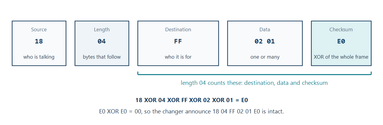
The same sum on the radio's poll of the changer gives 68 03 18 01 72. Source 68 is the radio, length 03 leaves room for the destination 18, the single data byte 01, and the checksum. A steering-wheel volume-up key, source 50 to the radio, closes as 50 04 68 32 11 1F. That last frame is also the volume-up frame published from a separate capture, which is the check that the XOR really does cover the source and the length and not only the data.
Text in a data field is ASCII. A space is 20. The field is not cleared before a new string is written, so the sender pads with spaces out to the width of that field. A short string otherwise leaves the tail of the previous one on screen.
Who is on it
Each module has a one-byte address. These are the addresses that appear in a frame whose checksum closes, or that the capture named and then used.
| Address | Module | What the frames show |
|---|---|---|
| 18 | CD changer | Announces itself, and answers the radio |
| 30 | Not named | Wrote a check-control line to the cluster |
| 3B | Navigation and video | Screen writes, disc-index selection, on-board computer reads |
| 50 | Multifunction steering wheel | Audio keys to the radio, telephone keys to the telephone |
| 68 | Radio | Polls the changer, writes the screen and the cluster text |
| 7F | Not named in the address list | The navigation system sent the position message to the telephone from this address |
| 80 | Instrument cluster | Text line, and the frames repeated to the light module |
| BF | Light control module | Destination of the cluster frames that close |
| C8 | Telephone | Steering-wheel dial key, the phone symbol, the position message |
| E7 | On-board computer text | The text line in the cluster, addressed as its own destination |
| F0 | Board monitor buttons | The keys around the navigation screen |
| FF | Broadcast | Changer announce, and the phone, menu and auxiliary-heater keys |
The same list names further addresses without a frame that would confirm them: 43 a menu screen, 60 park-distance control, 6A the digital sound processor, BB the television module, C0 the multi-information display buttons, D0 navigation location, and ED a combined lights, wipers and seat-memory entry. 3F, 44, A8 and E8 were left unnamed. 00 is also written down as a broadcast. Every broadcast frame in the capture uses FF.
Wilhelm's address list, which that project says is not authoritative, calls BF a global broadcast and D0 the lamp module. It publishes an announce from the lamp module to BF, D0 04 BF 02 01 68. The same list uses FF as a local broadcast. The E39 notes labeled destination BF as the light module, and every broadcast in that capture uses FF. A frame addressed to BF is still a frame the lamp module can act on, which is why the two names meet on the same bytes. Wilhelm also names 00 as the general body module, 30 as the E38 check-control module, 3F as the diagnostic gateway, 7F as the navigation computer, and E7 as the display multicast. Those names fit frames already on this page: 30 wrote the check-control line, 7F sent the position, and E7 is the text line. An address taken from another chassis needs a log from that chassis.
The cluster repeats a frame
The navigation module sends a five-byte payload to the cluster, and the cluster sends those same five bytes on to the light module with its own source, destination and checksum. Two pairs were captured.
| From | To | Frame |
|---|---|---|
| Navigation 3B | Cluster 80 | 3B 07 80 15 01 04 80 4A 66 |
| Cluster 80 | Light module BF | 80 07 BF 15 01 04 80 4A E2 |
| Navigation 3B | Cluster 80 | 3B 07 80 15 06 04 80 4A 61 |
| Cluster 80 | Light module BF | 80 07 BF 15 06 04 80 4A E5 |
The payload is 15 01 04 80 4A in the first pair and 15 06 04 80 4A in the second. What 01 and 06 distinguish was not identified. The cluster is the module on both sides of that repeat, which is why a log taken on the entertainment wire can contain light-module traffic.
Reverse is the same path. The cluster sent 80 0A BF 13 00 13 00 00 00 00 20 to the light module, one byte short of the length, when the mirrors moved on their own. The checksum that closes those bytes is 15, so the frame is 80 0A BF 13 00 13 00 00 00 00 20 15.
The cluster also broadcasts road speed and engine speed as command 18, addressed to BF, with two data bytes. The first byte times 2 is the speed in km/h. The second times 100 is rpm. FF in the speed byte is an invalid reading. 80 05 BF 18 41 19 7A is 130 km/h and 2,500 rpm. In that account the lamp module treats a speed byte of zero as stationary, and a brake-force display qualifier uses a threshold with 4 km/h of hysteresis. The E39 capture associated the video warning with about 5 km/h. Those are two descriptions of motion. Replaying a stopped-car frame is how that warning gets taken down while the car is moving, so a zero-speed frame is not given here.
Listening, and talking
A PC serial port is the wrong voltage and the wrong kind of driver. The wire sits near 12 V, and the device that talks has to let the wire go high on its own. A pin driven high fights every other module. Three interfaces were used against this capture.
A basic interface only shifts the level and pulls the wire down. It will log, and it will write, and it cannot tell that a second module started at the same moment.
A collision-detecting interface uses the RS-232 handshake. The program asserts RTS and waits until CTS is present before it sends. If CTS drops just after the send, another module had the wire. After a clean send the same bytes have to be sitting in the receive buffer: the talker hears its own low pulses, and that echo is the confirmation the frame went out intact. The circuit that did this used a MAX232A to translate the PC levels, with a 74HC27, a 74HC08, a 74HC04 and an RS latch. 74LS gates were also used in that build. One byte is a start bit, eight data bits, a parity bit and a stop bit, eleven bit-times, which at 9600 bit/s is 1.15 ms. The handshake has to be that quick.
A Melexis K-line transceiver does the collision detect in the chip. CTS low means the wire is already occupied.
A frame written onto the bus uses some module's source address, and that module is usually still connected. The echo and the collision check are what keep the two from talking at once. A string written to the navigation screen is the ordinary use of the bus. A frame the light module or the mirror logic acts on is a body command, on the same wire.
Steering wheel
The wheel is address 50. The cruise-control keys were not on this bus. The audio keys go to the radio, 68. The telephone keys go to the telephone, C8. Volume is a single code. The track and dial keys have a separate release, and the release sets bit 5 of the second data byte: 01 becomes 21, 08 becomes 28, and 80 becomes A0.
| Key | To | Press | Release |
|---|---|---|---|
| Volume down | Radio | 32 10 | |
| Volume up | Radio | 32 11 | |
| Next track | Radio | 3B 01 | 3B 21 |
| Previous track | Radio | 3B 08 | 3B 28 |
| Dial a number | Telephone | 3B 80 | 3B A0 |
| R/T | Telephone | 3B 40 |
Volume up, written out, is 50 04 68 32 11 1F. The data bytes above are the bytes after the destination. Length is 04 when there are two of them, because the destination and the checksum count as well.
Board monitor
The buttons around the navigation screen are address F0. A key is a two-byte payload. The first byte is 48 for a key, and the second byte is the key itself with the gesture in the top two bits. A press sends the key byte. Holding it past about a second sets bit 6, which adds 40. Releasing sets bit 7, which adds 80. Key 1 is 11, so the three frames carry 48 11, 48 51 and 48 91. The press, as a whole frame to the radio, is F0 04 68 48 11 C5.
| Key | Key byte | Sent to |
|---|---|---|
| 1 | 11 | Radio 68 |
| 2 | 01 | Radio 68 |
| 3 | 12 | Radio 68 |
| 4 | 02 | Radio 68 |
| 5 | 13 | Radio 68 |
| 6 | 03 | Radio 68 |
| Next track | 00 | Radio 68 |
| Previous track | 10 | Radio 68 |
| Tape reverse | 14 | Radio 68 |
| Eject | 24 | Radio 68 |
| AM | 21 | Radio 68 |
| FM | 31 | Radio 68 |
| RDS | 22 | Radio 68 |
| TP | 32 | Radio 68 |
| Dolby | 33 | Radio 68 |
| Mode | 23 | Radio 68 |
| Tone | 04 | Radio 68 |
| Select | 20 | Radio 68 |
| Radio menu | 30 | Radio 68 |
| Radio knob, press | 06 | Radio 68 |
| Navigation knob, press | 05 | Navigation 3B |
| Phone | 08 | Broadcast FF |
| Menu | 34 | Broadcast FF |
| Auxiliary heater timer | 07 | Broadcast FF, press only |
The phone key as a press is F0 04 FF 48 08 4B. The auxiliary-heater key was only captured as a press. Turning the radio on and off was not identified. The candidate recorded for it is 4B 05, and it was not confirmed.
The knobs rotate with a different first byte, and the second byte carries a step from 1 to 9 so that a fast turn is one message. The radio knob, still to the radio, sends 32 n0 for left and 32 n1 for right. That 32 is the same first byte the steering wheel uses for volume. The source address is what separates a knob from a wheel key. The navigation knob, to the navigation module, sends 49 0n for left and 49 8n for right.
A handful of bytes were captured with no key name. On the 48 family: 0C, 0D, 0E, 0F, 1A, 1B, 1C, 1D, 1E. On the 49 family: 21, 23, 61, 63, A1, A3, E1, E3.
The navigation screen
While the radio is the source, the Mk II screen is a set of fixed fields. The radio writes them. Nothing clears a field first.
| Field | Width |
|---|---|
| Area 0, the title | 11 characters |
| Areas 1 to 4 | 5 characters |
| Area 5 | 7 characters |
| Areas 6 and 7 | 20 characters |
| Index slots 0 to 9 | 14 characters |
The title write is 23 62 30 followed by the field. Whether 62 names the upper part of the screen, and whether 30 is the first of a run of indexes, was not settled. The same prefix is how the radio puts the CD title on the cluster text line. This frame was captured intact, source 68 to the cluster 80:
68 17 80 23 62 30 07 20 20 20 20 20 08 43 44 20 32 2D 30 34 20 20 BC 20 01
The ASCII in that field reads "CD 2-04". The bytes 07 and 08 sit in front of the pieces of the field, which is the form the capture used to join sub-fields. BC is a byte outside ASCII. The digit 4 in the title is already the ASCII byte 34, so BC is a further character, recorded as a special glyph.
Areas 1 to 7 are written with A5 62 01, then the area number 01 to 07, then the text, again padded by the sender. Refreshing the index area is the payload A5 60 01 00. The captured bytes are 68 06 3B A5 60 01 00, with the checksum left off. The byte that closes it is 91, so the frame is 68 06 3B A5 60 01 00 91.
The six-disc index is ten slots. Slots 1, 2, 3, 6, 7 and 8 are the discs. The other four are labels with no disc behind them.
| Slot | Label | Set byte | Press | Release |
|---|---|---|---|---|
| 0 | @ | 40 | 00 | 40 |
| 1 | A, CD 1 | 41 | 01 | 41 |
| 2 | B, CD 2 | 42 | 02 | 42 |
| 3 | C, CD 3 | 43 | 03 | 43 |
| 4 | D | 44 | 04 | 44 |
| 5 | E | 45 | 05 | 45 |
| 6 | F, CD 4 | 46 | 06 | 46 |
| 7 | G, CD 5 | 47 | 07 | 47 |
| 8 | H, CD 6 | 48 | 08 | 48 |
| 9 | I | 49 | 09 | 49 |
The radio fills one slot with 21 60 00, the set byte, and up to 14 characters. A longer write packed several labels into one frame with 06 between them. The tags 05, 07 and 08 were guessed as further steps and were not confirmed. A short radio-to-screen frame that does close is 68 06 3B 21 60 00 20 34, the same prefix followed by a single space.
Choosing a slot is the navigation module talking to the radio: 31 60 00 and the press or release byte from the table. Slot 1 pressed is 3B 06 68 31 60 00 01 05. Slots 1, 2, 3, 6, 7 and 8 are the ones that make the radio ask the changer for another disc.
As the radio switches off it sends 46 0C to the navigation module, which closes as 68 04 3B 46 0C 1D. A second code, 46 02, was noted without a confirmed effect. The navigation module turns its own picture off with a frame to the board monitor. The captured bytes are 3B 04 F0 4F 00, and the checksum that closes them is 80: 3B 04 F0 4F 00 80.
The CD changer
The changer is address 18. When the bus wakes it broadcasts an announce, data 02 01, every 30 seconds, until the radio polls it. The announce is the frame in the diagram above, 18 04 FF 02 01 E0. The poll is a single data byte, 68 03 18 01 72. The first answer is the poll response 02 00, broadcast as 18 04 FF 02 00 E1. After that the changer answers each poll, still about every 30 seconds. When the answers stop, the radio treats the changer as no longer fitted.
The radio's commands are short. The disc number is 01 to 06.
| Command | Data |
|---|---|
| Poll | 01 |
| Ask for disc and track | 38 00 00 |
| Stop | 38 01 00 |
| Play | 38 03 00 |
| Scan forward | 38 04 00 |
| Scan backward | 38 04 01 |
| Load disc nn | 38 06 nn |
| Intro scan on, off | 38 07 01, 38 07 00 |
| Random on, off | 38 08 01, 38 08 00 |
| Next track, previous track | 38 0A 00, 38 0A 01 |
38 02, 38 05 and 38 09 were not in the capture. Play is 38 03.
The changer reports to the radio with 39, a status byte, then 02 when stopped or 09 when playing, then 00 3F 00, then the disc and the track. Those three bytes were constant in this log and were not decoded. In the table, dd is the disc and tt is the track.
| Report | Data |
|---|---|
| Stopped | 39 00 02 00 3F 00 dd tt |
| Playing | 39 00 09 00 3F 00 dd tt |
| Track started | 39 02 09 00 3F 00 dd tt |
| Scanning forward | 39 03 09 00 3F 00 dd tt |
| Scanning backward | 39 04 09 00 3F 00 dd tt |
| Track ended | 39 07 09 00 3F 00 dd tt |
| Seeking | 39 08 09 00 3F 00 dd tt |
The current-status answer is the row that starts 39 00, and 02 against 09 is stopped against playing. The other rows are events. 39 01, 39 05 and 39 06 were not captured.
The text line in the cluster
A free line written to the cluster uses 1A 35 00 and then the ASCII, padded with spaces. The captured line was "CHECK CONTROL OK", from the unnamed source 30:
30 19 80 1A 35 00 20 20 43 48 45 43 4B 20 43 4F 4E 54 52 4F 4C 20 4F 4B 20 20 83
The on-board computer values are written to E7, the text destination, as 24, the parameter byte, 00, and the text. The navigation module reads and clears the same parameters on the cluster with 41, the parameter, a command, and an optional text. Command 01 reads the value. Command 10 resets it.
| Parameter | What was written | Sample |
|---|---|---|
| 01 | Time | 9:50 |
| 02 | Date | 19.11.2002 |
| 03 | Outside temperature | +6.5.C |
| 04 | Consumption | 9.4 L/100 |
| 05 | Consumption | 9.4 L/100 |
| 06 | Range | 541 KM |
| 07 | Distance | - 405 KM |
| 08 | Not named | --:-- |
| 09 | Limit | 170 KM/H |
| 0A | Average speed | 50.7 KM/H |
| 0E | Timer | 0.0 SEC |
| 0F | Auxiliary heater timer 1 | --:-- |
| 10 | Auxiliary heater timer 2 | --:-- |
| 1A | Not named | 0.0 SEC |
Parameters 04 and 05 were both recorded under the same name, with the same sample, so the difference between them was not established. The temperature sample is the characters "+6.5.C", dot included. The telephone lights its symbol in the same text line. The captured bytes are C8 04 E7 2C 11, and the checksum that closes them is 16: C8 04 E7 2C 11 16.
The word the cluster uses for the time follows the language. 00 was recorded as German, 01, 02 and 05 as the English word TIME, and 06 as the French HEURE. Spanish ORA and Italian HORA were queried against 03 and 04, so those two stay uncertain.
Position sent to the telephone
The navigation computer, source 7F, sends command A2 to the telephone, C8. The E39 notes called that message SPTI. Wilhelm's later captures call it telematics coordinates, and the frames there close. One of them is 7F 14 C8 A2 01 00 37 51 21 41 01 45 02 29 70 00 46 00 00 02 12 4F. Length 14 counts the 20 bytes that follow, and the XOR of the frame is 00.
After the command byte the payload is 17 bytes. Byte 0 is the fix: 01 means the receiver has a signal, 00 means the following fields may be zeros. Latitude is five BCD bytes: degrees, minutes, seconds, then a byte whose high nibble is the fraction of a second and whose low nibble is the sign. Longitude is the same shape. Altitude is two BCD bytes of metres. One byte is unused. The last three bytes are the time in BCD, hours, minutes and seconds, on a 24-hour UTC clock. A sign nibble of 0 is north or east. A sign nibble of 1 is south or west.
The frame above reads 37°51′21.4″S, 145°02′29.7″E, 46 m, at 00:02:12 UTC. The fix byte is 01, the latitude sign nibble is 1, and the longitude sign nibble is 0. Wilhelm says a later navigation computer sends this about every 30 seconds whether or not a telephone is fitted, and that an emergency call can carry the same coordinates onward as a text message. The E39 draft grouped these fields differently, and the bytes printed there were one byte away from a consistent length. This layout is the one whose published frames close.
Which cars use it
Two open-source projects publish the same chassis list. The Arduino I-bus library gives the E38 as 1994 to 2001. Wilhelm's document starts that row at 1999. The other rows agree. A car with both wires uses the instrument cluster to pass a frame from one to the other, chosen by the destination address. A car without navigation is the case both descriptions give for a K-bus on its own.
| Chassis | I-bus | K-bus |
|---|---|---|
| E31, 8 Series, 1989–1999 | Yes | |
| E38, 7 Series | Yes | Yes |
| E39, 5 Series, 1995–2004 | Yes | Yes |
| E46, 3 Series, 1997–2006 | Yes | |
| E52, Z8, 2000–2003 | Yes | |
| E53, X5, 1999–2006 | Yes | Yes |
| E83, X3, 2003–2010 | Yes | |
| E85, Z4, 2002–2008 | Yes | |
| E87, 1 Series, 2004–2013 | Yes |
node-ibus describes the same single-wire protocol on some Mini, Land Rover and MG cars, and it includes raw logs from a 2010 X3. Wilhelm's document says its own tables do not cover Mini or the early L322 Range Rover. The E46 in both BMW tables has the K-bus only, and the radio sits on that wire.
The address is one byte, shared by the I-bus, the K-bus and the diagnostic D-bus, and a given module keeps its address across those cars. Sharing the number does not put a D-bus module on the I-bus. The engine controllers live on the D-bus, which the workshop still calls TXD on older diagrams, and the cluster gateways diagnostic traffic onto it. Two further single wires are not this protocol. The P-bus is the general module's own link to its peripherals on the E38, E39 and E53. The M-bus runs the climate-flap stepper motors.
Announce and ping
Command 02 is how a module says it is present. The low bit of the following byte is 1 for an announcement and 0 for the reply to a ping. Command 01 is the ping. The higher bits of that 02 byte are a variant, used when another module has to tell the hardware apart. A module with no variants sends 01.
The E39 changer announced on FF with data 02 01. Wilhelm's later captures often announce on BF instead. The changer form there is 18 04 BF 02 01 A0. A telephone that identifies itself as a Motorola set broadcasts C8 04 FF 02 31 00. The wheel can then ping it, 50 03 C8 01 9A, and the telephone answers C8 04 50 02 30 AE. If the answers stop, the feature that module provided drops out of the menu. The same pattern is what the E39 radio uses when it decides the changer has gone.
Wilhelm's variant byte distinguishes, among other things, a graphics-stage video module (3B 04 FF 02 11 D3) from a navigation graphics stage, a 4:3 board monitor (F0 04 BF 02 01 48) from the later 16:9 sets, and a CMT telephone from the Motorola and Everest sets. The navigation computer's own announce is what tells the telephone whether BMW Assist is present.
Ignition, and the remote key
Command 11 is the cluster telling the bus which supply the key has closed. It is one data byte, sent to BF when the position changes, periodically while the bus is awake, in reply to command 10, and when a module announces itself. A blown fuse on the cluster's supply leaves this byte stuck, even if the key has moved. Navigation, in that account, will not wake on its accessory supply until the cluster has broadcast accessory.
| Key position | Data | Frame |
|---|---|---|
| 0, terminal 30 | 00 | 80 04 BF 11 00 2A |
| 1, terminal R | 01 | 80 04 BF 11 01 2B |
| 2, terminal 15 | 03 | 80 04 BF 11 03 29 |
| 3, terminal 50 | 07 | 80 04 BF 11 07 2D |
Command 72 is the general module reporting a remote-key button, again to BF. The high nibble is the button: 1 lock, 2 unlock, 4 the boot. Bits 1 to 3 are the key number, shifted up by one bit, so key 1 appears as 2. The low bit means the key battery is low. 00 04 BF 72 22 EB is unlock from key 1. 00 04 BF 72 10 D9 is lock with no key number in the byte. The Arduino library's own sample log prints the unlock frame as a good message.
The command byte
Byte 3 of a frame, the first data byte, is the command. The E39 tables above already use several of them. The open-source indexes give them these names. A command from one of those indexes still belongs to the cars that index was built from.
| Byte | Name in the project indexes | Where it already appears above |
|---|---|---|
| 01 | Ping | The radio's poll of the changer |
| 02 | Announce, or the reply to a ping | The changer's 02 01 and 02 00 |
| 11 | Ignition position | The cluster frames in the previous section |
| 18 | Speed and rpm | The cluster broadcast |
| 1A | Check-control text | The line written to the cluster |
| 21 | Menu text | The disc-index write |
| 23 | Title text | The screen title and the CD title |
| 24 | Property text | The on-board computer values |
| 32 | Volume, from the wheel, the knob or the amplifier | The wheel's 32 10 and 32 11 |
| 38 | CD-changer request | The radio's commands to the changer |
| 39 | CD-changer status | The changer's reports |
| 3B | Steering-wheel buttons | Track and telephone keys |
| 41 | On-board computer read and reset | The navigation module's 41 command |
| 48 | Board-monitor buttons | The 48 key family |
| 49 | Navigation knob | The 49 rotation family |
| 72 | Remote-key button | The general-module frames above |
| A2 | Telematics coordinates | The position message |
| A5 | Body text on the screen | The area writes that start A5 62 01 |
A Node client for the E39 treats on-board computer parameters 04 and 05 as consumption 1 and consumption 2. The E39 samples on this page used the same text for both, so that split is the client's and not something those samples showed.
Projects that talk to the wire
The bus sits at battery voltage. The projects that transmit use a transceiver, not a microcontroller pin. The Arduino library is built around a Melexis TH3122.4 or an ELMOS 10026B. TX of the transceiver goes to the UART receive pin, RX to the UART transmit pin, SEN/STA to an interrupt pin that times the idle gap, and EN to a pin that can power the transceiver down. On a Nano those are D0, D1, D3 and D4. The same library names a PC817 optocoupler circuit and an MCP2025 as ways to listen. Neither of those gives the SEN/STA idle signal the library wants before it will transmit.
The library is GPL-3, by Muksin Muksin. Its reader registers a handler and calls run from the main loop. The packet is the whole frame. This is the handler from that documentation, cut down to the volume key:
#include <BMW_IBus_KBus.h>

BMW_IBus_KBus ibus;

void startTimer() { ibus.startTimer(); }

void setup() {
  ibus.setIbusSerial(Serial);          // 9600 8E1 on the hardware UART
  ibus.setIbusPacketHandler(packetHandler);
  attachInterrupt(digitalPinToInterrupt(3), startTimer, CHANGE);
}

void loop() { ibus.run(); }

void packetHandler(byte *packet) {
  byte source = packet[0];
  byte destination = packet[2];
  byte command = packet[3];
  if (source == 0x50 && destination == 0x68 && command == 0x32) {
    // steering wheel to the radio, volume
  }
}
A frame stored without its checksum is queued and sent once the wire is idle. The library appends the XOR. This is its interior-light example, diagnostic gateway 3F to the general module 00. The completed frame is 3F 05 00 0C 01 01 36. It is a body command from that sketch, for the cars the sketch was tried on.
const byte Interior_On[] PROGMEM = {0x3F, 0x05, 0x00, 0x0C, 0x01, 0x01};

ibus.write(Interior_On, sizeof(Interior_On));
On an ESP32 the same library opens a second UART before attaching it. The documented call is Serial1.begin(9600, SERIAL_8E1, rxPin, txPin) and then ibus.setIbusSerial(Serial1). The library has been tried in an E46 on a Nano and on an ESP32-C6. Pico, STM32 and the UNO R4 compile, and had not been tried in a car when the readme was written.
node-ibus is a Node package for a serial adapter such as Resler's, on a Raspberry Pi or a PC. It has no licence file in the repository. It exposes each accepted frame as a source, a destination and the message bytes, and it will not write until the wire has been idle for more than 1.4 ms. The documentation's listener is:
var IbusInterface = require('ibus').IbusInterface;
var IbusDevices = require('ibus').IbusDevices;
var ibusInterface = new IbusInterface('/dev/ttyUSB0');

ibusInterface.on('data', function (data) {
  console.log(IbusDevices.getDeviceName(data.src),
              IbusDevices.getDeviceName(data.dst),
              data.msg);
});

ibusInterface.startup();
Walter is a GPL-3 Ruby stack on top of the Wilhelm library. Its low layer does the serial input and the frame check. A virtual layer models the modules, so a missing radio or a graphics stage can be emulated. A higher layer offers telephone, audio and display calls that do not take raw frames. It is a vehicle SDK, not a one-file decoder. node-bmw-client, which is MIT-licensed, covers the E38, E39, E46 and E53 in the same way: it can stand in for the CD changer, the multi-information display, the board monitor and the DSP controller, write a line to the cluster, and read the on-board computer values. It was developed against a 2000 540i and a 2002 M5 with Resler adapters. A companion library from the same author, node-bmw-interface, turns I-bus, K-bus, D-bus and CAN frames into JSON. The Arduino author also publishes a firmware that drives welcome lights and a small web page from an E46 log. That message table stays in the repository.
Sources
- I-BUS Inside. Franck Touanen, December 2002, draft revision 5. GNU General Public License, version 2. The E39 capture this page is rewritten from: the wire, the frame, the addresses, and the radio, changer, navigation, cluster and steering-wheel messages. Accessed 2026-11-12.
- BMW I-BUS Project. The volume-up frame
50 04 68 32 11 1F, the same XOR covering the whole frame. Accessed 2026-11-12. - CAN bus in the car, LIN bus in the car, the MOST optical bus, fibre-optic networks in the car, and BMW diagnostic connections.
- BMW I-Bus / K-Bus Library. Muksin Muksin, GPL-3. Chassis table, TH3122 wiring, the E46 CD-changer plug, the reader and the interior-light example. Accessed 2026-11-12.
- Wilhelm documentation. piersholt. Announce, ignition, speed, remote key, coordinates and the address list. The project says the document is not authoritative. Accessed 2026-11-12.
- node-ibus. osvathrobi. Serial listener, 1.4 ms idle gap, Resler adapter, 2010 X3 logs. No licence file in the repository. Accessed 2026-11-12.
- Walter. GPL-3 SDK built on Wilhelm. Accessed 2026-11-12.
- node-bmw-client. kmalinich, MIT. Module emulation and on-board computer fields on the E39. Accessed 2026-11-12.
- node-bmw-interface. kmalinich, MIT. I-bus, K-bus, D-bus and CAN frames as JSON. Accessed 2026-11-12.
- BMW I-Bus / K-Bus firmware. Muksin Muksin. Welcome lights and a web page driven from an E46 log. Accessed 2026-11-12.