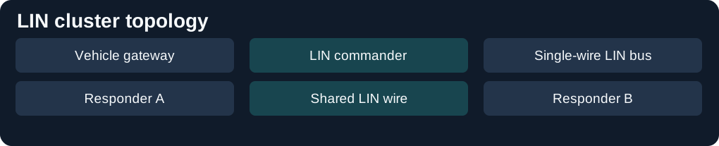
A LIN commander starts each frame by sending the header. The configured publisher supplies the response. A schedule determines when frames occur, which makes inexpensive subnets practical for switches and actuators.


Reading the network or diagnostic trace
A frame header includes a break, sync and protected identifier. When a response is missing, distinguish an absent header from a header that reached the bus without a response.
See CAN bus in the car and the vehicle diagnostics protocol guide.
Sources: ACTIA IME overview.
Detailed reference
LIN, the local interconnect network, is the slow single-wire bus under a faster one. A door, a climate flap, a wiper or a lamp node does not need CAN's pair or a fibre. One commander, which older writing calls the master, runs a schedule. Responders speak only when that schedule asks them to. BMW's aftersales bus manual lists it at 9.6 to 19.2 kbit/s, beside byteflight and MOST, which are the optical buses on the fibre-optic networks page.
What the specification covers
The LIN Consortium kept the specification through version 2.2A in 2010. Microchip's overview records the handover: in 2013 the text was taken into ISO, and ISO 17987 parts 1 to 7 were published in 2016. Supplier identifiers passed to SAE. ISO 17987-3, whose 2025 edition is the protocol specification, covers the commander and responder, the schedule table, status and error handling, and the node-configuration services that sit on UDS on LIN. The electrical layer is a separate part, ISO 17987-4, for 12 V and 24 V. A node on more than one LIN network is the application's problem. The protocol does not define it.
Microchip describes the implementation as a LIN transceiver, a UART, and an application controller. Responder nodes synchronise themselves from the frame, so they do not need their own crystal. The cluster is described in a LIN description file, which is the text the node suppliers build from. Bit rate is up to 20 kbit/s. The LIN Consortium's technology page narrows the allowed range to 1 kbit/s through 20 kbit/s, and takes 52 µs as the bit time at 19.2 kbit/s.
The frame
The commander sends the header. The response comes from one responder, or from the commander itself. The header is a break, an inter-byte space, the sync byte 0x55, the identifier, and a response space. The break has no start bit and no stop bit. Every other byte is 8 data bits, a start bit and a stop bit, and no parity. The response is the payload bytes and one checksum byte. Because the commander starts every frame, the cluster does not arbitrate. The time a signal will take is fixed by the schedule table before the car is built.
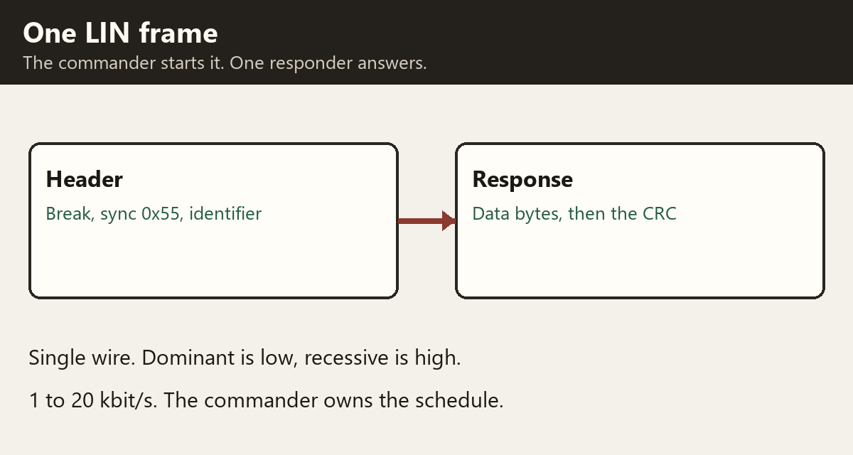
The two levels use the same words as CAN, with the polarity stated by the consortium: recessive is a logical high, dominant is a logical low. A single wire is easier to disturb than a differential pair, which is why the rate stays in this band and why LIN is the bus for the flap motor rather than for the crankshaft sensor.
Sleep, and where it sits in the car
The bus is either asleep or active. While a frame is on the wire, every node is supposed to be active. After the timeout they sleep. Any node can send the wake-up, the commander because its schedule says so, or a responder because its own software has something to report. Once the nodes are awake, the commander carries on with the next frame in the table.
BMW's bus manual puts LIN among the sub-buses, with the K-bus protocol, the BSD and the DWA bus, all single-wire and all at a few tens of kilobits at most. The main buses in that table are CAN at 100 or 500 kbit/s, byteflight at 10 Mbit/s and MOST at 22.5 Mbit/s. A gateway is the interface between them. A LIN cluster for the air-conditioning motors, which is Microchip's example of the arrangement, never appears as its own pins on the emissions connector. The scan tool reaches it through the control unit that is the commander, and that control unit is the one on CAN or on the diagnostic bus. What that commander will pass on, and the three kinds of responder it may be talking to, are on the LIN diagnostics page.
A published teardown of a 2019 Tesla Model 3 uses LIN in the same role: ultrasonic sensors, a temperature and humidity sensor, the overhead consoles, the front and rear lamp controllers, the wiper and HomeLink. The CAN trunks and the Ethernet on that car are on the Ethernet and DoIP page. The LIN clusters there are still local. They are not the network the body controllers use to talk to each other.
The protected identifier and the checksum
The identifier the commander sends is one byte. The low six bits are the frame identifier, 0 to 63. Bits 6 and 7 are a parity over those six, so a flipped identifier is visible before any data byte arrives. With the identifier bits numbered from ID0, the least significant, the two parity bits are ID0 xor ID1 xor ID2 xor ID4, and the inverse of ID1 xor ID3 xor ID4 xor ID5. Identifiers 0 to 59 carry signals. 60 and 61, 3C and 3D hexadecimal, carry diagnostics and configuration, described on the LIN diagnostics page. 62 and 63 are reserved.
The data field is one to eight bytes, least significant byte first when a signal spans more than one byte. The length is fixed for that identifier. It is agreed in the cluster file, not announced in the frame. Unused bits inside a frame are sent recessive.
The checksum is an eight-bit sum with the carry added back: add the bytes, and each time the sum passes 255, subtract 255, then invert the result. A classic checksum covers the data bytes only. An enhanced checksum covers the data bytes and the protected identifier. LIN 1.x responders use the classic checksum. LIN 2.x signal frames use the enhanced checksum. Frames 3C and 3D always use the classic checksum, whichever generation the rest of the cluster is. The commander decides per identifier. A 2.x commander can keep a 1.3 responder in the cluster by using the classic checksum for that responder's frames, and by not asking it for reconfiguration, automatic baud detection or a response-error bit. A 2.x responder needs a commander that will send the enhanced checksum. A 1.3 commander will not.
From LIN 2.0 a responder can publish a response-error bit in a frame of its own. It sets the bit when it has seen a faulty frame, and the commander reads it on a later pass of the schedule. There is no automatic retransmission. The next slot is the next chance.
Unconditional, event-triggered and sporadic
An unconditional frame is the ordinary one. Whenever its slot comes round, the commander sends the header and the publisher always answers. One publisher, any number of listeners. A door-switch poll that must be fresh every 15 ms is this kind of slot, and the answer comes back every 15 ms whether the switch moved or not.
An event-triggered frame is one header for several responders that rarely have news. Each associated unconditional frame has the same length and the same checksum, is published by a different responder, and keeps its own protected identifier in the first data byte. A responder answers only when one of its signals has changed. If nobody answers, the rest of the slot is silent. If two answer, the bytes collide. The commander then runs a collision schedule made of those unconditional frames, one publisher at a time, and returns to the previous table at the following entry. A door lock with four buttons is the usual example: one poll covers all four, and the collision schedule is only needed when two passengers press together.
A sporadic frame is a slot the commander itself owns. Several unconditional frames share it. If none of them has a new signal, the slot stays empty. If one has, that frame is sent. If several have, the commander sends the highest priority and keeps the others pending for the next time the slot comes round. There is no collision, because only the commander publishes. The window motor that only needs to be asked while it is moving is this kind of slot.
The schedule and the clock
The schedule table is a list of slots. Each slot starts on a tick of the commander's time base, commonly 5 ms or 10 ms, and the slot length is a whole number of those ticks. The slot has to be longer than the longest legal frame plus the commander's jitter, so a slow break and a full eight-byte answer still finish before the next header. At the end of the table the commander starts again at the top, unless the application has asked for a different table. The switch happens at a slot boundary. A header already on the wire is left to finish.
The nominal header is 34 bit times: a 13-bit dominant break, a one-bit recessive delimiter, the sync byte and the protected identifier. A responder recognises a break as at least 11 of its own bit times dominant, or 9.5 if its clock is already tight. The response is ten bit times for every data byte and ten more for the checksum. The gaps inside the frame may stretch the header and the response to 1.4 times those nominal times. A listener has to accept a frame with no gaps at all, and it has to keep listening up to the next break even if the frame runs long. The commander is responsible for the table still having room.
The nominal rate is chosen for the cluster, anywhere from 1 kbit/s to 20 kbit/s. The commander's clock stays within 0.5 percent of that rate. A responder with its own accurate clock, and no use of the sync byte, stays within 1.5 percent. A responder that will synchronise may be 14 percent off before it sees the sync byte, which is why a cheap on-chip oscillator is enough to notice the break. After the sync byte it has to stay within 2 percent of the commander for the rest of the frame. The sync byte is 55 hexadecimal, and the falling edges are two bit times apart, so the responder measures the bit time from those edges. Two responders talking to each other, which happens when one publishes a frame the other subscribes to, also have to stay within 2 percent of each other.
The wire, sleep and wake-up
The transceiver is the ISO 9141 idea with tighter edges. The line is pulled up to the battery through a diode and a resistor, about 1 kilohm in the commander and about 30 kilohm in each responder. The diode stops a powered line from feeding an unplugged module. Recessive is that pull-up. Dominant is a transistor to ground. A receiver treats a level above about 60 percent of the sender's supply as recessive and a level below about 40 percent as dominant, so a ground shift between modules still leaves a gap between the two states. The commander and the responders can share the wire with a generation older than themselves at this electrical level. A node built to the 2.2 electrical rules can sit in a 1.3 cluster.
The cluster is awake or asleep. A responder that sees the bus stay recessive for 4 to 10 seconds, or that receives the go-to-sleep command, enters sleep. The go-to-sleep command is a master-request frame whose first data byte is zero. Any node may wake the cluster with a dominant pulse of 250 microseconds to 5 ms. The others treat a dominant pulse longer than 150 microseconds, followed by the rising edge, as the wake-up, and a responder has to be ready for headers within 100 ms of that edge. If the commander does not start a header, the node that asked may try again after 150 to 250 ms. The commander then resumes the schedule. A break is itself long enough to be seen as a wake-up, so the first header after sleep may be missed by a responder that is still starting, and the commander sends it again in the normal table.
Sources
- LIN technology. LIN Consortium. Commander and responder, the header and checksum, 1 to 20 kbit/s, recessive and dominant. Accessed 2026-11-12.
- LIN overview. Microchip. Version 2.2A, the move to ISO 17987, UART nodes, and the description file. Accessed 2026-11-12.
- ISO 17987-3:2025. Protocol specification, schedule tables, and UDS-on-LIN node configuration. Accessed 2026-11-12.
- LIN Specification Package, revision 2.2A, 31 December 2010. Protected-identifier parity, classic and enhanced checksums, unconditional, event-triggered and sporadic frames, the 34-bit header, the bit-rate tolerances, and the wake-up pulse. Later published as ISO 17987.
- Bus systems. BMW Aftersales Training. LIN at 9.6 to 19.2 kbit/s as a sub-bus. Accessed 2026-11-12.