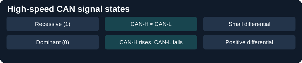
High-speed CAN uses a differential pair. Nodes share the same bus and arbitrate access by comparing transmitted and observed bits. A dominant bit overrides a recessive bit.

Reading the network or diagnostic trace
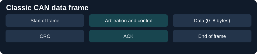
Classic CAN carries up to eight data bytes per frame. The identifier participates in arbitration and can identify a broadcast message or form part of diagnostic addressing. On a conventional high-speed bus, termination belongs at the two ends of the trunk.

See CAN bus ID database and the vehicle diagnostics protocol guide.
Sources: ACTIA IME overview.
Detailed reference
CAN, the controller area network, is the copper bus a workshop meets on the powertrain, the chassis and, on many cars, the body. A message carries an identifier. Every node on that wire can read it, and the nodes that care about the identifier act on it. The physical layer on a high-speed bus is two wires, CAN_H and CAN_L, driven as a difference. It is not a fibre, and it is not LIN. Fibre rings are on the fibre-optic networks page. The diagnostic services that ride on CAN are on the diagnostic communication protocols page. A long reply on that bus is split on the ISO-TP page. Volkswagen Group modules that open a channel first are on the TP 2.0 page. A timetable over the same frames is time-triggered CAN. The pulse bus that shared the American emissions socket is SAE J1850. The transceivers, the controllers beside them, and the choke and clamp on the same copper are on the CAN transceivers page. For vehicle-specific CAN arbitration identifiers and payload layouts by make and model, see the CAN bus ID database.
Two wires, two levels
CAN in Automation describes the high-speed transceiver, in use since 1992, as the physical medium attachment now specified in ISO 11898-2. The maximum bit rate of that classic transceiver is 1 Mbit/s. On CAN_H and CAN_L the recessive state drives both lines nominally to 2.5 V. The dominant state drives CAN_H nominally to 3.5 V and CAN_L nominally to 1.5 V. CiA gives the dominant differential range as 0.9 V to 2.0 V and the recessive differential range as −1.0 V to 0.5 V. The span from 0.5 V to 0.9 V is indifferent. A transceiver may be supplied from 5 V or from 3.3 V. CiA says the 3.3 V supply is not yet standardised, and that the two supplies can share a network.

The recommended layout is a line, terminated at both ends with 120 ohm to match the cable. CiA also describes a split termination, two 60 ohm resistors with a capacitor to ground. A car's termination is part of its wiring. Adding a resistor because a generic drawing shows 120 ohm, without that car's diagram, is how a bus gets a third terminator and starts to fail at the far end.
Bit rate and length are tied together by the arbitration method. At 1 Mbit/s CiA's theoretical reach is 40 m, and real cables, connectors and transceivers make it shorter. The sample point matters. Slowing the bus lengthens the cable, until around 1 km the voltage drop itself stops a dominant bit being seen, and the conductor has to be thicker. CiA asks for a cable delay of no more than 5 ns/m.
What a car actually runs
The 1 Mbit/s figure is the classic transceiver's ceiling. A manufacturer picks a lower rate for the network it is building. BMW's E65 bus module, for the 745i from November 2001, publishes PT-CAN at 500 kbit/s and both K-CAN System and K-CAN Periphery at 100 kbit/s. PT-CAN on that car is the powertrain pair plus a terminal-15 wake-up wire, so the loom has three wires even though the CAN itself is still the pair. K-CAN replaced the earlier single-wire body bus. Those rates are that module's. A later BMW aftersales manual repeats 500 kbit/s for PT-CAN and 100 kbit/s for K-CAN, and lists a separate F-CAN at 100 kbit/s. The diagnostic bus on the E65 module is 115 kbit/s and is not the CAN pair.
The emissions connector assigns the high-speed pair to pins 6 and 14. That assignment, and the pins left to the manufacturer, are on the diagnostic ports page. A second CAN inside the car does not appear on those two pins. K-CAN on the E65 is a different pair, reached through a gateway.
Arbitration, then the data
While several nodes may start together, the bit rate has to leave time for every node to see the same bit. CiA's account of CAN FD puts the consequence plainly: the higher rate is available only once a single node is left transmitting, because the others no longer have to be synchronised to it. Classic CAN, which CiA calls CAN CC, stays at one rate for the whole frame and is limited to 1 Mbit/s. The identifier is the field the nodes use to decide who continues. A dominant bit wins over a recessive bit, which is why the voltage levels above are not just a signalling choice. They are how two transmitters share one pair without a master handing out turns.
ISO 11898-1:2024, as CiA cites it, standardises classic CAN and CAN FD together. A CAN FD frame uses an 11-bit identifier in the FD base format or a 29-bit identifier in the FD extended format. The FD-format bit selects which kind of frame follows. Recessive means CAN FD. Dominant means a classic data frame or remote frame. The bit-rate-switch bit, when recessive, applies the second rate from that point. CAN FD does not support remote frames. The payload grows from the classic 8 bytes to as many as 64. The cyclic redundancy check grows with it: 17 bits up to 16 bytes of payload, 21 bits above that, plus a stuff-bit counter. CiA notes that non-ISO CAN FD controllers omit those extra checks and are not ISO 11898-1.
The data-phase rate is set by the transceiver and the wiring, not by a single number in the protocol. CiA's high-speed page distinguishes a classic transceiver, suitable up to 1 Mbit/s, from a CAN FD transceiver with tighter symmetry for rates above 1 Mbit/s, including 2 Mbit/s and above. A ratio of 1:8 between the arbitration rate and the data-phase rate is the example CiA uses for roughly six times the throughput, once the longer header and checksum are counted. Arbitration itself stays at or below 1 Mbit/s. CiA's later physical-layer list adds a signal-improvement transceiver, CAN SIC, specified in ISO 11898-2:2024 with the data phase limited to 5 Mbit/s, and a CAN XL transceiver whose fast mode uses pulse-width modulation and can reach 20 Mbit/s if the wiring allows. Those options can hold arbitration down to 667 kbit/s when every identifier has to be permitted. They are transceiver choices. They are not the rate of an E65 powertrain bus.
CiA also notes that fibre-optic and power-line CAN exist, and that those specifications are proprietary. The BMW and Mercedes buses cited here are the copper pair.
Sleep, and the other physical layers
A high-speed transceiver can have a low-power mode, originally ISO 11898-5 and later merged into ISO 11898-2. A bus signal wakes every node. Selective wake-up, originally ISO 11898-6 and also merged into ISO 11898-2:2016, wakes a chosen subset with a dedicated frame, which is how a mirror or a window node can stay asleep on a motorway. CiA calls that partial networking. It is a transceiver feature. It is not present just because the car has CAN.
CiA's physical-layer list also includes a low-speed fault-tolerant transceiver, ISO 11898-3, at a maximum of 125 kbit/s, which it no longer recommends for new designs; a truck and trailer transceiver, ISO 11992-1, at 125 kbit/s; and single-wire CAN, SAE J2411, also no longer recommended for new designs. Low-speed fault-tolerant CAN, the ISO 11898-3 transceiver, uses a larger swing on each wire than the 2 V differential of the high-speed pair. The termination sits in the nodes, stubs can be longer, and a node can keep reading a wire when the other is open. A high-speed layout is the twisted pair with 120 ohm at the two ends, and the stubs stay short, on the order of 30 cm at the top of the speed range, so a reflection dies inside the bit. Single-wire CAN, SAE J2411, is one wire against ground, 33.3 kbit/s in its normal mode and 83.3 kbit/s in its high-speed mode. Those are different electrical layers. A tool set up for the high-speed pair will not speak them by being plugged into the same diagnostic socket.
Diagnostic services on CAN use the transport in ISO 15765-2, set out on the ISO-TP page. The services themselves stay the ones on the protocols page. CAN FD and classic CAN can share a controller. A control unit built for classic frames stays silent through an FD frame.
The bit
The signalling is NRZ. The level stays where it was put for the whole bit, and the nodes recover the clock from the edges. A bit is divided into time quanta. The first quantum is the sync segment. A propagation segment follows, long enough for the round trip to the far node and back, because arbitration only works if every node sees the same bit before the sample. Two phase segments sit after that, and the sample point is the boundary between them. A controller may lengthen or shorten a phase segment by one quantum when an edge arrives early or late, which is how the nodes stay locked without a shared clock wire. At 500 kbit/s a common setting is a 125 ns quantum and 16 quanta in the bit, which puts the sample point well past the middle. The propagation segment has to grow as the cable grows, which is why the 1 Mbit/s reach on the high-speed page is a few tens of metres and a slower bus can run further.
Frames, stuff bits and the error flag
A data frame starts with one dominant start bit. Then the identifier, 11 bits in the base format or 29 bits in the extended format, then the control bits, including the four that count the data bytes. The payload is 0 to 8 bytes on a classic frame. A 15-bit cyclic redundancy check follows, then a recessive delimiter. In the acknowledge slot the transmitter sends recessive, and any node that saw a valid check drives the slot dominant. Seven recessive bits end the frame, and three more recessive bits of intermission separate it from the next one. A remote frame uses the same identifier and carries no data. It asks whoever publishes that identifier to send the data frame. Powertrain buses in cars broadcast the data frame on a timer and leave the remote frame unused. An overload frame sits in the intermission and asks the others to pause. It is rare on a modern controller.
From the start bit through the check, five identical bits in a row are followed by a stuff bit of the opposite level. Receivers remove it. The edges it creates are what the bit timing locks to, and a stuff error is one of the ways a damaged frame is seen. An error flag is six dominant bits with no stuff bit, which is illegal in a data frame, so every node notices it, discards the frame, and adds its own flag. Eight recessive bits then delimit the error. The transmitter retries. A node that finds itself causing the errors counts them and, past the protocol's limit, stops transmitting until it has watched the bus run cleanly. The checks together, the stuff rule, the frame form, the cyclic redundancy check and the acknowledge, are the reason a published residual for an undetected CAN error is on the order of one in 1011. That figure is the protocol's design claim. It is not a measurement of one car's wiring.
At 500 kbit/s a classic extended data frame with eight payload bytes occupies a few hundred microseconds on the wire, on the order of 260 microseconds before stuff bits. The useful rate is far below 500 kbit/s, because the identifier, the check and the gaps travel with every eight bytes. A long diagnostic reply is many of these frames. How they are grouped is the transport, on the ISO-TP page and, for the Volkswagen Group channel, the TP 2.0 page.
Which frames a node keeps
A node has no address of its own. It keeps a frame when the identifier matches a filter: a bit pattern, and a mask that says which bits of that pattern matter. The polarity of the mask, whether a 1 means "compare" or "ignore", depends on the controller. An SJA1000-style mask and a later controller can use opposite conventions for the same word. The filter in the tool has to be read from that controller's manual. A node that is only interested in the powertrain identifiers can ignore the rest in hardware, which is why a log of "everything on the pair" needs the filter opened, and a log of one control unit needs it closed to that unit's diagnostic identifiers.
Sources
- CAN high-speed transmission. CAN in Automation. ISO 11898-2 levels, 1 Mbit/s, 120 ohm, length, low-power and selective wake-up. Accessed 2026-11-12.
- CAN FD, the basic idea. CAN in Automation. Arbitration limit, 64-byte payload, FDF and BRS, ISO 11898-1:2024. Accessed 2026-11-12.
- Physical layer options. CAN in Automation. Fault-tolerant, truck and trailer, and single-wire transceivers. Accessed 2026-11-12.
- E65 Bus Systems. BMW technical training. PT-CAN at 500 kbit/s and K-CAN at 100 kbit/s. Accessed 2026-11-12.
- ISO 11898-1. The classic data frame, the remote frame, bit stuffing after five identical bits, and the six-bit error flag.