Tuning Wiki

This is a historical revision. Read the current page or return to its history.

Page organisation in this revision
Page type
Technical article
Subject
Carb Tuning
Parent
Section level
Applies to
No ECU-specific applicability
Tool groups
None
Manufacturers
None

Changes from revision 8 to revision 8

Removed text is struck through; added text is highlighted.

The Weber DCOE (Doppio Corpo Orizzontale, double-body horizontal) and racing DCO/SP series are synchronous twin-choke sidedraft carburettors. Almost always installed so each throttle barrel feeds one individual cylinder runner, they combine interchangeable main venturis, auxiliary venturis, emulsion wells, idle progression jets and mechanical accelerator pumps in a compact alloy casting.
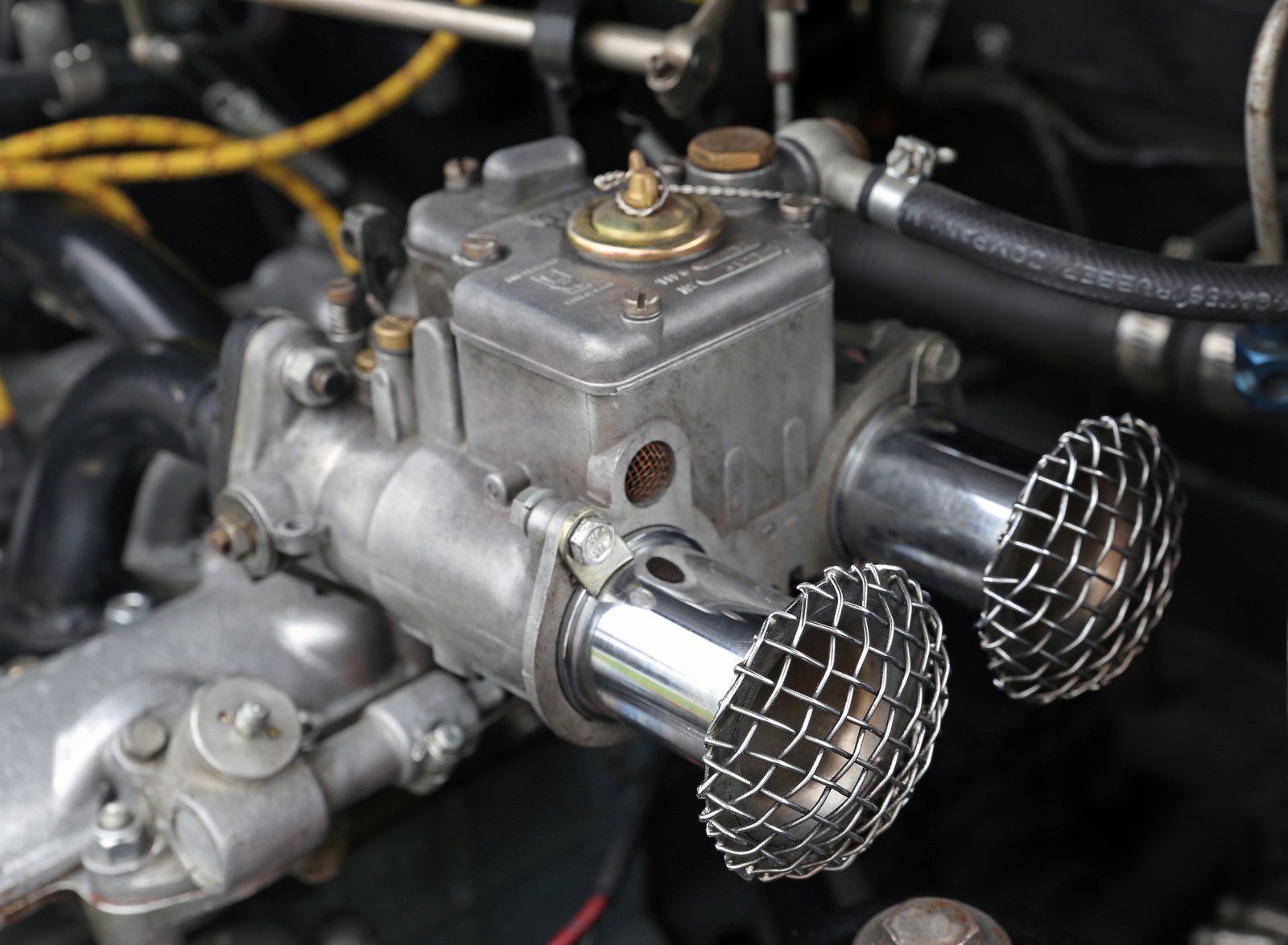
Weber 40 DCOE sidedraft carburettor mounted on an Abarth 1000 Bialbero twin-cam. Photo: Mr.choppers, resized; Wikimedia Commons, CC BY-SA 3.0.

Weber 45 DCOE 9 sidedraft body showing trumpets and top jet-cover access. Photo: Reforma.imufomot, Wikimedia Commons, Public domain.

Adjustment screw diagram

Weber 45 DCOE 9: the two spring-loaded idle mixture screws, shown from above. The idle-speed linkage is outside this view. Original simplified redraw for Tuning Wiki, CC BY 4.0, from the public-domain photograph by Reforma.imufomot; control identification cross-checked against Redline’s DCOE diagram. Check the exact model; not to scale.

View Redline's DCOE adjustment-control diagram. The labelled view identifies the idle speed screw, the two idle mixture screws and the air-bypass screws and locknuts. Scroll to “DCOE Adjustment controls”. This is a typical DCOE layout; confirm the precise variant and linkage before applying it to a DCO/SP.

50 DCO/SP and 1/SP: Carburetion.com exploded drawing and parts key identifies the throttle-stop screw as item 36, mixture screws as 41, and air-bypass screws as 64. Confirm the exact carburettor number before applying the drawing to another DCO/SP size or version.

1. Choke (venturi) & barrel sizing

Power potential and low-RPM tractability are governed primarily by the removable main venturi (choke), not the outer barrel diameter (Dave Andrews Weber DCOE guide). Ideal throttle-barrel size is approximately venturi size × 1.25 (for example, a 36 mm choke pairs ideally with a 45 DCOE, though a 40 DCOE can also fit a 36 mm choke).

ModelAvailable chokesFactory baseline example (choke / main / em. tube / air / idle / pump / needle) 40 DCOE 15124–36 mm32 mm / 115 / F11 / 200 / 45F9 / 40 pump (50 bleed) / 1.75 42 DCOE24–34 mm32 mm / 135 / F15 / 155 / 55F2 / 45 pump / 2.00 (Maserati 3500 GT) 45 DCOE 15228–40 mm36 mm / 145 / F16 / 155 / 55F8 / 45 pump (40 bleed) / 2.00 48 DCOE40–42 mm42 mm / 180 / F9 / 160 / 60F8 / 45 pump (100 bleed) / 2.50 48 / 50 DCO/SP42–46 mm42 or 46 mm / 180 / F7 / 160 / 65F8 / 45 pump (100 bleed) / 2.50 55 DCO/SP46–48 mm48 mm / 180 / F9 / 180 / 60F8 / 45 pump (100 bleed) / 2.50

2. Float level & fuel pressure

Fuel pressure: keep regulated delivery pressure around 2.5–3 psi; excessive pump pressure forces fuel past the needle valve and floods the auxiliary venturis. Dry float height (lid vertical, gasket fitted, tang touching ball without compressing spring): 40 / 45 DCOE brass float: typically 8–9 mm closed / 14–15 mm drop (5–8 mm on some early 45 DCOE models; verify exact float weight and casting type). 40 / 45 DCOE / DCO-SP plastic float: typically 12.5 mm closed / 25 mm drop (12 mm on 48/50/55 DCO/SP plastic float, Bigorre float chart; Pierce Manifolds). Wet fuel-level check: with the emulsion tube removed, an acrylic optical depth gauge in the emulsion well typically reads 25 mm ± 1 mm below the top deck (Weber DCOE reference).

3. Idle, progression & the 2,500–3,000 rpm stumble

Close air-bypass screws first: on late emissions-type DCOE 151/152 bodies with air-bleed bypass screws under 8 mm locknuts, lightly seat them closed before base idle setup. Idle speed stop & Lean Best Idle: keep the idle speed stop no more than ¼–½ turn past contact (so the throttle butterfly does not uncover progression holes at idle). Start mixture screws at 1 turn out (2.5 turns on coarse-thread early DCOEs). Tune each barrel individually for smoothest, fastest idle. Synchronise carbs: match airflow with a Synchrometer or Uni-Syn by bringing the higher-flowing carb down to the lower-flowing carb, then adjust both evenly to target idle (900–1,100 rpm on cammed engines). Fix 2,500–3,000 rpm stumble with the F-bleed: Webcon UK notes that the DCOE idle jet's numeric prefix (e.g. 50 = 0.50 mm) sets idle fuel flow so the mixture screw sits around 1–3 turns out, whereas the F-number sets the side air-bleed hole controlling upper progression just before the main circuit cuts in. Keep the fuel number fixed and step between F8 (1.2 mm, leanest), F9 (1.0 mm, standard start) and F6 (0.7 mm, richest) to cure a lean misfire or rich stumble around 2,500–3,000 rpm.

4. Main jet, emulsion tube & air corrector tuning

Starting formulas: main jet ≈ venturi (mm) × 4; air corrector ≈ main jet + 50. Emulsion tubes by cylinder size: 250–325 cc → F11; 275–400 cc → F15; 350–475 cc → F9 or F16; 450–575 cc → F2. Splitting roles: tune the main jet (Weber 41110.001) for full-load mid-to-upper RPM AFR, then use the air corrector (77401 / 41360 series) to flatten the top-end slope (larger leans high RPM, smaller enriches high RPM).

5. Related pages

Weber carburettor tuning overview Weber IDF carburettors: specs and tuning Weber IDA and IDA 3C carburettors: specs and tuning Carburettor synchronisation, faults and rebuilds

Sources

Weber Carburettors Type 38–48 DCOE Manual. D. V. Andrews: Selection and Tuning of Weber DCOE Carburettors. Webcon UK: Fixing 2500–3000 rpm DCOE Stumble/Misfire and Baseline Weber Jetting Chart. Bigorre Carburateur Float Heights and Pierce Manifolds Float Level Sheet.

Rendered revisions

Open each version to inspect formatting, tables and photographs.

Revision 8: Weber DCOE and DCO-SP carburettors: specs and tuning

The Weber DCOE (Doppio Corpo Orizzontale, double-body horizontal) and racing DCO/SP series are synchronous twin-choke sidedraft carburettors. Almost always installed so each throttle barrel feeds one individual cylinder runner, they combine interchangeable main venturis, auxiliary venturis, emulsion wells, idle progression jets and mechanical accelerator pumps in a compact alloy casting.
Weber 40 DCOE twin-choke sidedraft carburettor on Abarth 1000 Bialbero
Weber 40 DCOE sidedraft carburettor mounted on an Abarth 1000 Bialbero twin-cam. Photo: Mr.choppers, resized; Wikimedia Commons, CC BY-SA 3.0.
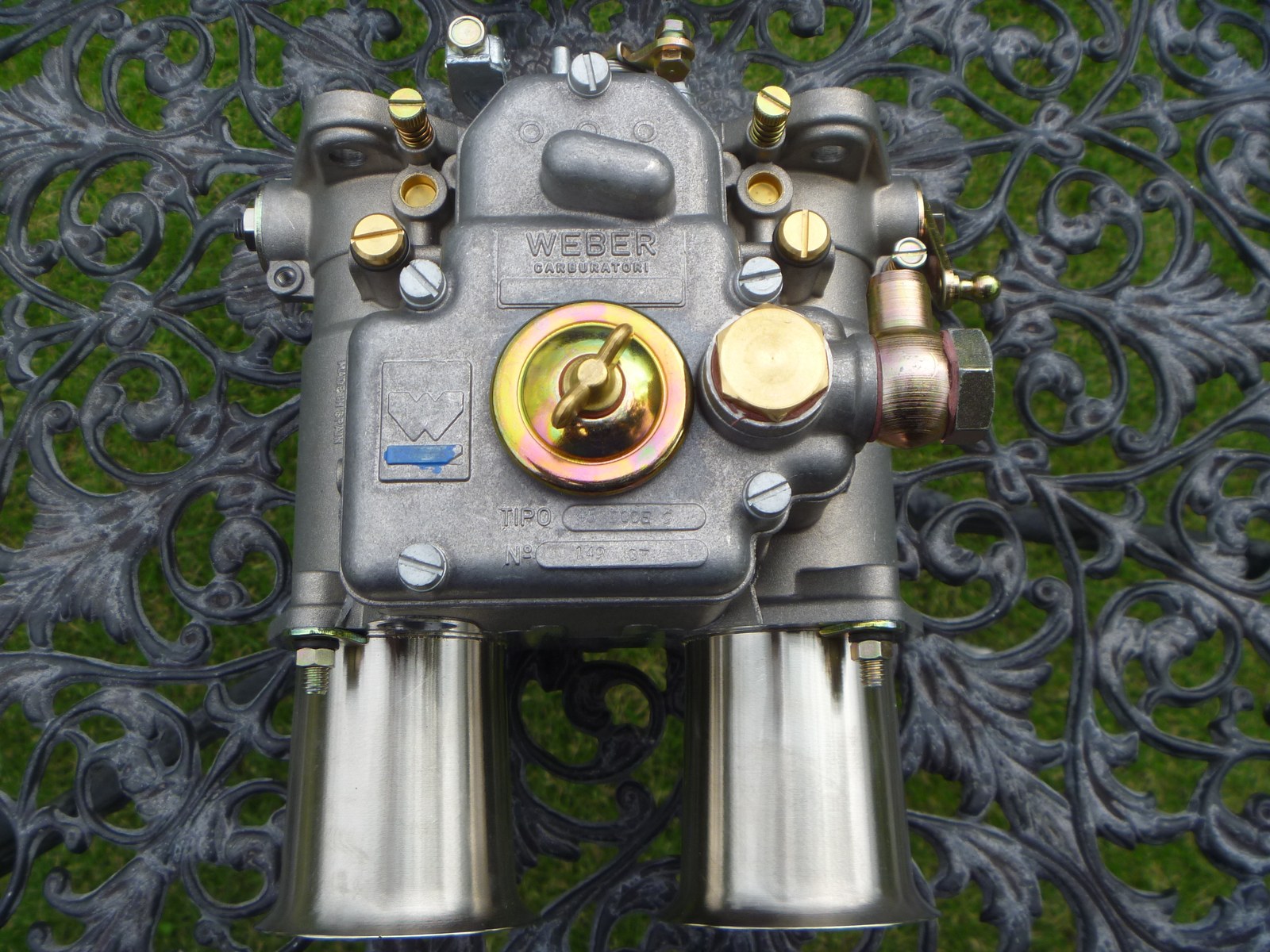
Weber 45 DCOE 9 carburettor body showing air horns and top jet inspection cover
Weber 45 DCOE 9 sidedraft body showing trumpets and top jet-cover access. Photo: Reforma.imufomot, Wikimedia Commons, Public domain.

Adjustment screw diagram

Weber 45 DCOE 9 top-view schematic, highlighting two idle mixture screws on the engine side
Weber 45 DCOE 9: the two spring-loaded idle mixture screws, shown from above. The idle-speed linkage is outside this view. Original simplified redraw for Tuning Wiki, CC BY 4.0, from the public-domain photograph by Reforma.imufomot; control identification cross-checked against Redline’s DCOE diagram. Check the exact model; not to scale.

View Redline's DCOE adjustment-control diagram. The labelled view identifies the idle speed screw, the two idle mixture screws and the air-bypass screws and locknuts. Scroll to “DCOE Adjustment controls”. This is a typical DCOE layout; confirm the precise variant and linkage before applying it to a DCO/SP.

50 DCO/SP and 1/SP: Carburetion.com exploded drawing and parts key identifies the throttle-stop screw as item 36, mixture screws as 41, and air-bypass screws as 64. Confirm the exact carburettor number before applying the drawing to another DCO/SP size or version.

1. Choke (venturi) & barrel sizing

Power potential and low-RPM tractability are governed primarily by the removable main venturi (choke), not the outer barrel diameter (Dave Andrews Weber DCOE guide). Ideal throttle-barrel size is approximately venturi size × 1.25 (for example, a 36 mm choke pairs ideally with a 45 DCOE, though a 40 DCOE can also fit a 36 mm choke).

ModelAvailable chokesFactory baseline example (choke / main / em. tube / air / idle / pump / needle)
40 DCOE 15124–36 mm32 mm / 115 / F11 / 200 / 45F9 / 40 pump (50 bleed) / 1.75
42 DCOE24–34 mm32 mm / 135 / F15 / 155 / 55F2 / 45 pump / 2.00 (Maserati 3500 GT)
45 DCOE 15228–40 mm36 mm / 145 / F16 / 155 / 55F8 / 45 pump (40 bleed) / 2.00
48 DCOE40–42 mm42 mm / 180 / F9 / 160 / 60F8 / 45 pump (100 bleed) / 2.50
48 / 50 DCO/SP42–46 mm42 or 46 mm / 180 / F7 / 160 / 65F8 / 45 pump (100 bleed) / 2.50
55 DCO/SP46–48 mm48 mm / 180 / F9 / 180 / 60F8 / 45 pump (100 bleed) / 2.50

2. Float level & fuel pressure

  • Fuel pressure: keep regulated delivery pressure around 2.5–3 psi; excessive pump pressure forces fuel past the needle valve and floods the auxiliary venturis.
  • Dry float height (lid vertical, gasket fitted, tang touching ball without compressing spring):
    • 40 / 45 DCOE brass float: typically 8–9 mm closed / 14–15 mm drop (5–8 mm on some early 45 DCOE models; verify exact float weight and casting type).
    • 40 / 45 DCOE / DCO-SP plastic float: typically 12.5 mm closed / 25 mm drop (12 mm on 48/50/55 DCO/SP plastic float, Bigorre float chart; Pierce Manifolds).
  • Wet fuel-level check: with the emulsion tube removed, an acrylic optical depth gauge in the emulsion well typically reads 25 mm ± 1 mm below the top deck (Weber DCOE reference).

3. Idle, progression & the 2,500–3,000 rpm stumble

  1. Close air-bypass screws first: on late emissions-type DCOE 151/152 bodies with air-bleed bypass screws under 8 mm locknuts, lightly seat them closed before base idle setup.
  2. Idle speed stop & Lean Best Idle: keep the idle speed stop no more than ¼–½ turn past contact (so the throttle butterfly does not uncover progression holes at idle). Start mixture screws at 1 turn out (2.5 turns on coarse-thread early DCOEs). Tune each barrel individually for smoothest, fastest idle.
  3. Synchronise carbs: match airflow with a Synchrometer or Uni-Syn by bringing the higher-flowing carb down to the lower-flowing carb, then adjust both evenly to target idle (900–1,100 rpm on cammed engines).
  4. Fix 2,500–3,000 rpm stumble with the F-bleed: Webcon UK notes that the DCOE idle jet's numeric prefix (e.g. 50 = 0.50 mm) sets idle fuel flow so the mixture screw sits around 1–3 turns out, whereas the F-number sets the side air-bleed hole controlling upper progression just before the main circuit cuts in. Keep the fuel number fixed and step between F8 (1.2 mm, leanest), F9 (1.0 mm, standard start) and F6 (0.7 mm, richest) to cure a lean misfire or rich stumble around 2,500–3,000 rpm.

4. Main jet, emulsion tube & air corrector tuning

  • Starting formulas: main jet ≈ venturi (mm) × 4; air corrector ≈ main jet + 50.
  • Emulsion tubes by cylinder size: 250–325 cc → F11; 275–400 cc → F15; 350–475 cc → F9 or F16; 450–575 cc → F2.
  • Splitting roles: tune the main jet (Weber 41110.001) for full-load mid-to-upper RPM AFR, then use the air corrector (77401 / 41360 series) to flatten the top-end slope (larger leans high RPM, smaller enriches high RPM).

5. Related pages

Sources

Revision 8: Weber DCOE and DCO-SP carburettors: specs and tuning

The Weber DCOE (Doppio Corpo Orizzontale, double-body horizontal) and racing DCO/SP series are synchronous twin-choke sidedraft carburettors. Almost always installed so each throttle barrel feeds one individual cylinder runner, they combine interchangeable main venturis, auxiliary venturis, emulsion wells, idle progression jets and mechanical accelerator pumps in a compact alloy casting.

Weber 40 DCOE twin-choke sidedraft carburettor on Abarth 1000 Bialbero
Weber 40 DCOE sidedraft carburettor mounted on an Abarth 1000 Bialbero twin-cam. Photo: Mr.choppers, resized; Wikimedia Commons, CC BY-SA 3.0.
Weber 45 DCOE 9 carburettor body showing air horns and top jet inspection cover
Weber 45 DCOE 9 sidedraft body showing trumpets and top jet-cover access. Photo: Reforma.imufomot, Wikimedia Commons, Public domain.

Adjustment screw diagram

Weber 45 DCOE 9 top-view schematic, highlighting two idle mixture screws on the engine side
Weber 45 DCOE 9: the two spring-loaded idle mixture screws, shown from above. The idle-speed linkage is outside this view. Original simplified redraw for Tuning Wiki, CC BY 4.0, from the public-domain photograph by Reforma.imufomot; control identification cross-checked against Redline’s DCOE diagram. Check the exact model; not to scale.

View Redline's DCOE adjustment-control diagram. The labelled view identifies the idle speed screw, the two idle mixture screws and the air-bypass screws and locknuts. Scroll to “DCOE Adjustment controls”. This is a typical DCOE layout; confirm the precise variant and linkage before applying it to a DCO/SP.

50 DCO/SP and 1/SP: Carburetion.com exploded drawing and parts key identifies the throttle-stop screw as item 36, mixture screws as 41, and air-bypass screws as 64. Confirm the exact carburettor number before applying the drawing to another DCO/SP size or version.

1. Choke (venturi) & barrel sizing

Power potential and low-RPM tractability are governed primarily by the removable main venturi (choke), not the outer barrel diameter (Dave Andrews Weber DCOE guide). Ideal throttle-barrel size is approximately venturi size × 1.25 (for example, a 36 mm choke pairs ideally with a 45 DCOE, though a 40 DCOE can also fit a 36 mm choke).

ModelAvailable chokesFactory baseline example (choke / main / em. tube / air / idle / pump / needle)
40 DCOE 15124–36 mm32 mm / 115 / F11 / 200 / 45F9 / 40 pump (50 bleed) / 1.75
42 DCOE24–34 mm32 mm / 135 / F15 / 155 / 55F2 / 45 pump / 2.00 (Maserati 3500 GT)
45 DCOE 15228–40 mm36 mm / 145 / F16 / 155 / 55F8 / 45 pump (40 bleed) / 2.00
48 DCOE40–42 mm42 mm / 180 / F9 / 160 / 60F8 / 45 pump (100 bleed) / 2.50
48 / 50 DCO/SP42–46 mm42 or 46 mm / 180 / F7 / 160 / 65F8 / 45 pump (100 bleed) / 2.50
55 DCO/SP46–48 mm48 mm / 180 / F9 / 180 / 60F8 / 45 pump (100 bleed) / 2.50

2. Float level & fuel pressure

  • Fuel pressure: keep regulated delivery pressure around 2.5–3 psi; excessive pump pressure forces fuel past the needle valve and floods the auxiliary venturis.
  • Dry float height (lid vertical, gasket fitted, tang touching ball without compressing spring):
    • 40 / 45 DCOE brass float: typically 8–9 mm closed / 14–15 mm drop (5–8 mm on some early 45 DCOE models; verify exact float weight and casting type).
    • 40 / 45 DCOE / DCO-SP plastic float: typically 12.5 mm closed / 25 mm drop (12 mm on 48/50/55 DCO/SP plastic float, Bigorre float chart; Pierce Manifolds).
  • Wet fuel-level check: with the emulsion tube removed, an acrylic optical depth gauge in the emulsion well typically reads 25 mm ± 1 mm below the top deck (Weber DCOE reference).

3. Idle, progression & the 2,500–3,000 rpm stumble

  1. Close air-bypass screws first: on late emissions-type DCOE 151/152 bodies with air-bleed bypass screws under 8 mm locknuts, lightly seat them closed before base idle setup.
  2. Idle speed stop & Lean Best Idle: keep the idle speed stop no more than ¼–½ turn past contact (so the throttle butterfly does not uncover progression holes at idle). Start mixture screws at 1 turn out (2.5 turns on coarse-thread early DCOEs). Tune each barrel individually for smoothest, fastest idle.
  3. Synchronise carbs: match airflow with a Synchrometer or Uni-Syn by bringing the higher-flowing carb down to the lower-flowing carb, then adjust both evenly to target idle (900–1,100 rpm on cammed engines).
  4. Fix 2,500–3,000 rpm stumble with the F-bleed: Webcon UK notes that the DCOE idle jet's numeric prefix (e.g. 50 = 0.50 mm) sets idle fuel flow so the mixture screw sits around 1–3 turns out, whereas the F-number sets the side air-bleed hole controlling upper progression just before the main circuit cuts in. Keep the fuel number fixed and step between F8 (1.2 mm, leanest), F9 (1.0 mm, standard start) and F6 (0.7 mm, richest) to cure a lean misfire or rich stumble around 2,500–3,000 rpm.

4. Main jet, emulsion tube & air corrector tuning

  • Starting formulas: main jet ≈ venturi (mm) × 4; air corrector ≈ main jet + 50.
  • Emulsion tubes by cylinder size: 250–325 cc → F11; 275–400 cc → F15; 350–475 cc → F9 or F16; 450–575 cc → F2.
  • Splitting roles: tune the main jet (Weber 41110.001) for full-load mid-to-upper RPM AFR, then use the air corrector (77401 / 41360 series) to flatten the top-end slope (larger leans high RPM, smaller enriches high RPM).

5. Related pages

Sources