Fixed-choke Zenith carburettors—including the updraft/downdraft VIG, 24-T2, IZ / IV / VN and early compound-jet series (distinct from the later rubber-diaphragm Zenith-Stromberg CD units)—were original equipment on decades of British and European cars, vans and tractors. Zenith's own service bulletins set out clear calibration and diagnostic rules (Zenith 24-T2 guide; Zenith IZ guide).
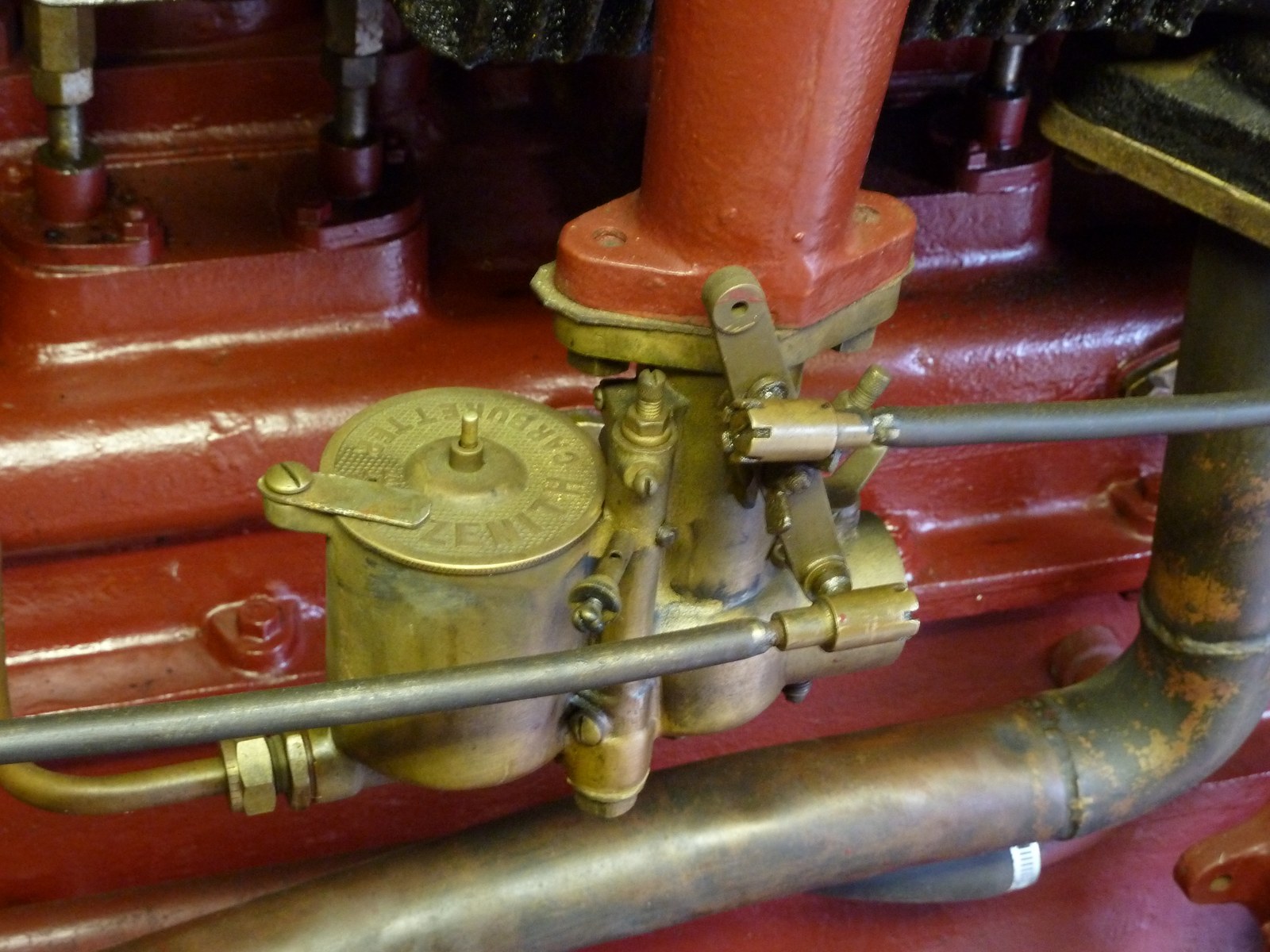


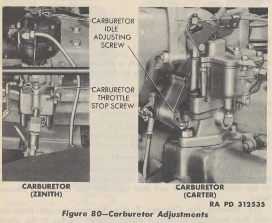
Adjustment screw diagrams by Zenith model
Use the stamped model and suffix to choose the diagram: Zenith used different idle circuits and screw locations across the range. The original labelled illustrations below are published by Zenith Carburetters / Burlen; follow the links to view them.
- 24-T2: Labelled exterior diagram shows the throttle stop screw and air-regulating screw, plus an adjustable main jet on the version equipped with one. See the 24-T2 service guide for the circuit and the distinction between fixed and adjustable main jets.
- IZ: Labelled exterior diagram identifies the throttle adjustment screw and idle volume-control screw. The IZ service guide describes the volume screw at the fixing flange on the engine side of the throttle.
- 30 VIG-5 and 30 VIG-8: Side-by-side labelled diagrams distinguish the VIG-5 volume-control screw from the VIG-8 air-regulating screw and show the throttle adjustment. Other suffixes differ; use the model table in the 30 VIG service bulletin.
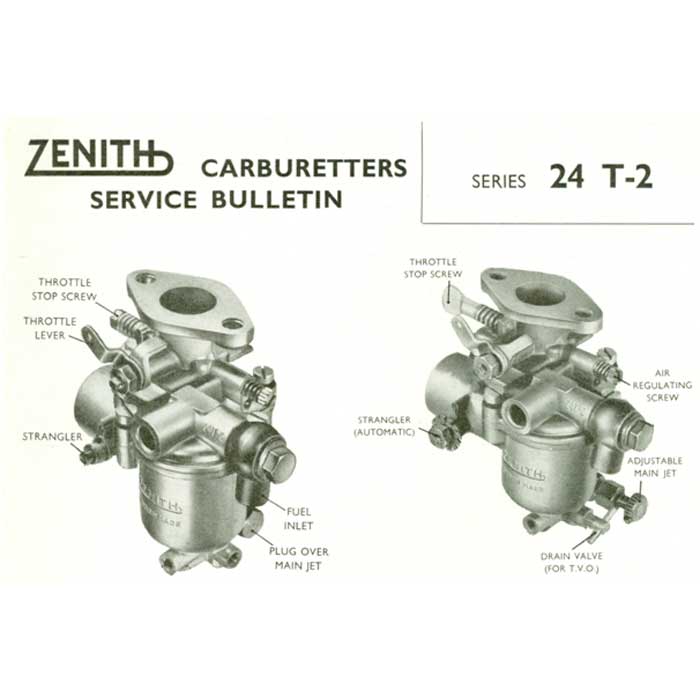
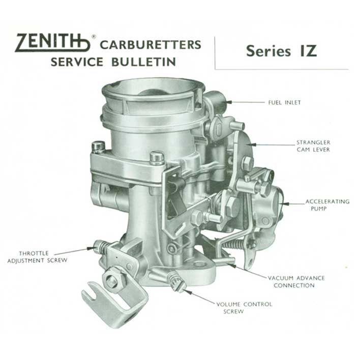

The illustrations show particular versions, not every Zenith variant. Confirm the exact model and its service information before adjusting a screw.
1. Jet & choke-tube numbering conventions
- Jets and air bleeds in hundredths of a millimetre: on fixed-choke Zeniths such as the
24-T2, main and slow-running jets are calibrated in units of0.01 mm(typically in steps of 5, so a95jet is larger than a90). Standard air jets are commonly100, 120, 150, 175, 200, 250and300, with half-sizes (e.g.97between95and100) used for fine tuning. - Choke tubes (venturis): marked inside the throat in millimetres indicating the smallest bore diameter (for example
12 mmto20 mmin1 mmsteps on the24-T2). - Progression & emulsion drillings: unlike modular Weber DCOE emulsion tubes, many OEM Zenith castings fix the progression hole sizes and emulsion drillings in the body during factory calibration; mixture remains constant only while those internal passages stay clean and the carburettor body is unworn.
2. Essential workshop precautions
- Verify electricals & tappets before touching jets: Zenith manuals repeatedly stress checking contact-breaker gaps, ignition timing, spark plugs, cylinder compression, tappet clearances and manifold joint tightness first—electrical and mechanical faults are routinely misdiagnosed as carburettor trouble (Zenith 30 VIG guide).
- Never ream, drill or hammer jets: even if a jet carries the right stamped number, previous tampering with wire drills or punches ruins its calibration. Replace any suspect jet with a genuine part of known flow (Zenith Service Guide).
- Manifold heating on vertical carburettors: Zenith's service guide highlights that vertical carburettors without functioning manifold heat (exhaust hotspot or water jacket) suffer fuel condensation on the manifold walls, making slow running, clean pick-up and even distribution almost impossible to tune.
- Gummed needle valves after standing: if a vehicle refuses to start after sitting and the float bowl is dry, fuel evaporation may have left sticky gum holding the needle valve shut. Removing the top half and rinsing the needle and seat in methylated spirit dissolves gum deposits and frees the valve (Zenith IZ servicing).
- Choke / strangler linkage checks: verify that the intake strangler flap closes fully when the dashboard choke is pulled; some Zenith linkages incorporate spring-loaded lost-motion couplings rather than a rigid direct arm to the flap spindle.
3. Zenith compound-jet principle (historic models)
Early Zenith carburettors pioneered François Baverey's compound-jet (compensating-jet) design to solve the basic physics problem of a simple fixed jet, which goes progressively richer as air speed rises. Zenith placed two jets feeding the choke: a main jet fed directly from the float chamber (growing richer at higher airflow) and a compensating jet fed through a gravity-restricted orifice into an open atmospheric well (delivering a constant volume per second, which therefore leans out as airflow increases). Combined, the two opposite curves produced a much flatter mixture across the speed range.
Related pages
- Carburettors (section overview)
- Carburettor types and layouts
- Carburettor makes and model families
- Carburettor tuning, jetting and setup
- Carburettor synchronisation, faults and rebuilds
Sources
- Zenith Carburetters / Burlen Ltd: Zenith 24-T2 Operation & Maintenance Guide. Jet and choke calibration conventions and wear inspection.
- Zenith Carburetters / Burlen Ltd: Zenith IZ Operation, Servicing & Troubleshooting. Gummed needle valves and strangler checks.
- Zenith Series 30 VIG Technical Guide and Zenith Carburetter Service Guide. Manifold heating, non-reamering rules and pre-tuning engine checks.