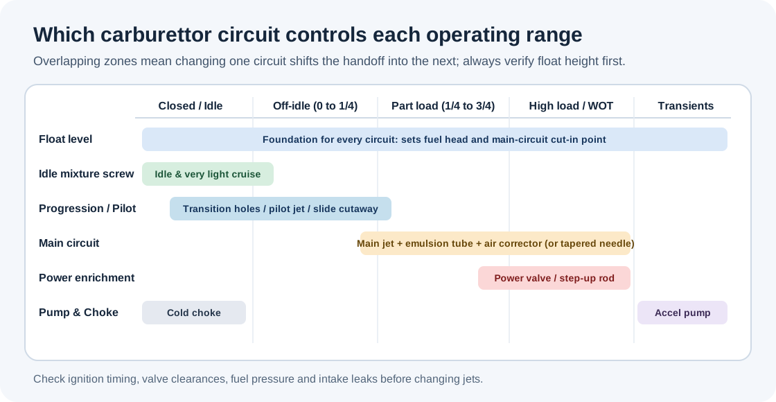
A carburettor has to keep fuel atomised and near the target air-fuel ratio across a huge range of airflow—from a 700 rpm idle to redline at wide-open throttle, plus cold starts and rapid pedal movements. Because fuel flow and air flow do not scale linearly across a single orifice, carburettors divide the job into overlapping circuits.
1. Float chamber and fuel level
Before any jetting circuit works properly, the float bowl must hold fuel at a steady height below the discharge nozzle. A float (hollow brass, plastic or closed-cell nitrophyl) operates a needle valve against incoming pump or gravity pressure. If the fuel level sits too high, fuel rises closer to the nozzle lip, so less venturi depression is needed to draw it—making every circuit richer and causing fuel to drip or flood at idle or on corners. If the level sits too low, the engine leans out across transitions and runs dry under sustained load.
Manufacturers specify float setting either as a dry height/drop dimension with the carburettor inverted or tilted (common on Holley, Edelbrock, Mikuni VM and Keihin FCR/PWK carbs, taking care not to compress the spring-loaded needle pin while measuring) or as a wet fuel level below the top deck (for example, checking the Weber DCOE emulsion-well fuel height with a depth gauge).
2. Idle and progression (transfer) circuits
At idle and tiny throttle openings, air speed through the main venturi is too low to pull fuel from the main discharge nozzle. Instead, high manifold vacuum below the closed throttle butterfly draws fuel through an idle jet (or slow jet), mixes it with air from an idle air bleed, and discharges it through:
- The idle mixture port downstream of the throttle plate, adjusted by a tapered screw.
- Progression holes or transfer slots just at and slightly above the throttle plate edge.
As the throttle blade cracks open from idle, it sweeps past the progression holes/slot, exposing them one by one to manifold vacuum. This bridges the gap before the main venturi begins flowing. A common setup mistake is winding the idle speed stop screw too far in to make a big-cam engine idle: that uncovers the transfer slot at idle, puts the carburettor onto the progression circuit prematurely, makes the idle mixture screws unresponsive, and causes an off-idle stumble.
Fuel screw vs air screw: on most automotive carbs (Weber, Holley, SU HIF/HS idle jet screw, Keihin FCR), the idle screw sits on the engine side and meters fuel-air emulsion—turning it out richens the idle. On many two-stroke and older slide carbs (such as Keihin PWK/CR/PE or Mikuni VM air screws), the screw sits on the airbox side and meters air—turning it out leans the mixture (Sudco Keihin tuning guide).
Adjustment-screw diagrams: Holley and Rochester
Use the diagrams for the identified carburettor and vehicle application. Idle and choke controls can differ between versions.
- Holley 4150 Ultra XP: Holley installation and adjustment instructions, figures 2–4B, pages 5–6, show primary and secondary idle-speed adjustments and the four idle-mixture screws. The Ultra XP also has an idle-bypass valve; other 4150 versions may differ.
- Rochester Quadrajet 4M, 4MC and 4MV: Rochester service manual 9D-5, figure 27, labels the idle-speed adjusting screw and mixture screws on an example unit; figure 41 labels the mixture screws and fast-idle screw on the throttle body. Controls and accessibility vary by application and later models may have limiter caps or sealed screws.
3. Main circuit, emulsion tubes and air correctors
As airflow rises through the main venturi (or auxiliary venturi/booster), local static pressure falls and draws fuel up from the float bowl through the main jet. Without compensation, raw liquid through a simple jet would go progressively richer as airflow and depression increase.
Fixed-choke carburettors counter this with an emulsion tube and air corrector jet sitting in a vertical well:
- At rest, fuel stands inside the emulsion well at the same height as the float bowl.
- Once main-circuit flow begins, the level in the well drops, uncovering rows of cross-drilled holes in the emulsion tube.
- Air admitted through the top air corrector jet enters the emulsion tube holes, mixes with fuel into a light froth (emulsion) that atomises cleanly at the auxiliary venturi, and limits excessive fuel draw at high engine speeds (Weber DCOE manual).
In general, the main jet sets overall richness once the main circuit is active (especially mid-to-upper load), while the air corrector tilts the high-RPM slope (a larger air corrector leans out the top end, while a smaller air corrector enriches high RPM). Emulsion tube outer diameter and hole placement alter when the main circuit starts and how the mixture behaves through the mid-range transition.
4. Variable-choke and slide-throttle mid-range metering
Variable-choke (SU, Zenith-Stromberg, motorcycle CV) and mechanical slide-throttle (Amal, Mikuni VM/TM, Keihin PWK/FCR) carbs use throttle-area variation and a tapered needle moving inside a calibrated orifice (jet or needle jet) instead of emulsion-tube staging:
- SU / Stromberg: piston lift follows airflow; the needle's cylindrical root governs idle/light cruise (together with jet height), while successive tapered stations along the needle set part-load and full-load mixture. A damper plunger filled with oil briefly slows upward piston motion when the throttle snaps open, raising air velocity over the jet momentarily to create enrichment without a separate accelerator pump.
- Mechanical slide carbs: throttle position directly sets the zone: 0–1/8 is dominated by pilot jet and air/fuel screw; 1/8–1/4 by slide cutaway (smaller cutaway number = richer); 1/4–3/4 by needle diameter, clip position (lowering the clip raises the needle and richens the mid-range) and needle jet; and 3/4–WOT by the main jet.
5. Power enrichment circuits
Cruising on light throttle wants a lean, economical mixture (typically around 14.5–15.5:1 AFR on older road engines), whereas climbing a hill or running at wide-open throttle requires a cooler, richer power mixture (typically around 12.5–13.2:1 naturally aspirated) to prevent knock and overheating. Four-barrel and two-barrel road carburettors bridge those two targets with a vacuum-sensitive enrichment circuit:
- Holley power valve: a spring-loaded diaphragm valve held shut by manifold vacuum. When vacuum drops below the valve's rating (for example 6.5 in Hg on a "65" power valve), the spring opens the valve and feeds extra fuel through the power valve channel restrictions (PVCR) into the main circuit (Holley power valve guide).
- Carter / Edelbrock / Rochester metering rods: vacuum pistons pull tapered or stepped rods down into the main jets at high-vacuum cruise (reducing orifice area) and let springs lift the thinner step out of the jet when vacuum falls under load (Edelbrock tuning guide; Quadrajet manual).
6. Accelerator pump and cold-start choke
- Accelerator pump: when the throttle snaps open, manifold vacuum collapses faster than heavier fuel droplets can accelerate down the manifold. A mechanical diaphragm or plunger pump squirts raw fuel into the throat via calibrated pump jets/shooters. Pump cam shape controls timing and total volume; nozzle diameter controls squirt rate and duration.
- Cold-start enrichment: cold manifold walls condense petrol out of the air stream, leaving too little vapour to burn. Fixed-choke carbs either close an upstream strangler butterfly (choke flap) linked to a fast-idle cam—creating strong depression across the nozzles—or open a dedicated starter enrichment passage. SU HS units lower the entire jet assembly away from the tapered needle, whereas SU HIF units use a progressive rotary enrichment valve.
Related pages
- Carburettors (section overview)
- Carburettor types and layouts
- Carburettor tuning, jetting and setup
- Carburettor synchronisation, faults and rebuilds
Sources
- Weber Carburettors DCOE Manual. Progression drillings, emulsion well operation and main/air corrector interaction.
- Holley Power Enrichment System Technical Note. Power valve ratings and vacuum actuation.
- Edelbrock Performer / AVS Tuning Guide. Step-up metering rods, springs and accelerator pump calibration.
- Sudco Carburetor Tuning Guide. Fuel screw vs air screw distinction and slide-carb circuit ranges.
- Burlen Ltd: SU Design Features and HIF Technical Reference.