An inertia dynamometer measures the rate at which a test engine or vehicle accelerates a rotating mass of known moment of inertia. The rotating drum or flywheel stores kinetic energy. Unlike an adjustable brake on its own, an inertia is a load whose torque depends on how quickly its speed changes. A dynamometer may combine an inertia drum with an adjustable absorber; the two contributions must both be considered.

The physics
For a known constant rotational inertia J, angular acceleration α produces net accelerating torque T = Jα. The stored kinetic energy is E = ½Jω² and the rate of increase is P = Jαω, with J in kg·m², ω in rad/s, α in rad/s², T in N·m and power in watts. A speed sensor records drum rotation over time and the system derives angular acceleration. The Dynojet WinPEP theory of operation explains the use of drum speed and acceleration in an inertia dyno.
For example, if the effective test inertia is 10 kg·m², its speed is 100 rad/s and its angular acceleration is 20 rad/s², its net accelerating torque is 200 N·m and the rate of energy storage is 20 kW. This ideal example excludes friction, added brake load and any inertia not included in J.
From roller acceleration to vehicle output
The measured acceleration gives torque accelerating the dyno inertia, not automatically all torque produced by the engine. Friction, windage, tyre/roller losses and any applied brake consume torque. Engine, drivetrain, wheel and coupling inertias also accelerate during a sweep, and their effect at the measurement point depends on gearing and slip. The calculation and any loss or inertia corrections must match the machine and measurement boundary. Engine rpm requires a separate pickup or a justified relationship to roller speed. SAE 2017-36-0212 discusses experimental determination of chassis-dyno inertia and losses.
Sweep rate and steady state
A pure inertia system generally performs an acceleration sweep: torque causes the drum to accelerate, with acceleration varying across the run. Under sustained positive input torque it cannot hold a chosen steady speed by inertia alone. An added controllable absorber can hold or shape the speed trajectory within its torque, power and thermal limits. Sweep rate matters because an engine's boost, temperature and control response may change with time, and because acceleration consumes energy in rotating parts. Smoothing acceleration data can also alter peaks.
Repeatability
Use the correct calibrated inertia and speed signal, repeat gear and run procedure, control vehicle and dyno temperatures, and check tyre condition and restraint on a roller machine. Record correction standard, sweep method and RPM source. Results from inertia-only, load-controlled and engine dynamometers can differ for legitimate reasons; their reported numbers should be compared with their measurement methods and conditions.
See also: Dynamometers overview · Rolling roads · Engine dynamometers · Hub dynamometers · On-car and portable systems · Inertia dynamometers.
Manufacturer example
Advanced Dyno Solutions describes a 2WD two-roller inertia chassis dyno with an SP1 electronics package. The listing is an example of an inertia-only configuration; confirm equipment and availability directly with the supplier.
Example manufacturer: Dynojet 224xLC combines an inertia-based roller system with an eddy-current load absorber, illustrating that the two methods can be used together.
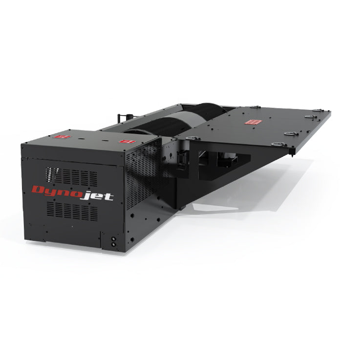
Equivalent road mass and gearing
If a roller of effective radius r rotates without tyre slip, its surface speed is v = rω. Matching its rotational energy ½Jω² to the translational energy ½mv² gives the roller’s equivalent mass m = J/r². This is the mass equivalent of the stated roller inertia at its surface, not the vehicle’s complete mass or necessarily the total inertia of the whole test system. The effective inertia of components on another shaft must be referred to the measurement shaft using the square of their speed ratio; be careful not to count an included flywheel twice.
For example, Dyna Pro lists the S68 with a 453 mm diameter roller and 7.0 kg·m² inertia. Taking its radius as 0.2265 m gives 7.0 ÷ 0.2265² ≈ 136 kg roller-equivalent mass, consistent with the maker’s modelled-mass figure. This illustration excludes extra rotating parts and tyre slip.
Working from a recorded speed sweep
Convert rotational speed in revolutions per minute to angular speed using ω = 2π × rpm / 60. Over an interval, average angular acceleration is Δω/Δt. A 7.0 kg·m² inertia increasing from 1,000 to 1,300 rpm in three seconds has an average α of about 10.47 rad/s² and net accelerating torque of about 73 N·m. If acceleration is constant, at the midpoint of 1,150 rpm (about 120.4 rad/s) the instantaneous storage rate is approximately 8.8 kW. These illustrative figures exclude friction, other rotating inertia and brake torque; actual software must account for the machine’s measurement boundary and processing.
Using smaller speed intervals provides more detail but makes differentiation more sensitive to sensor noise and time resolution. Filtering can improve readability yet obscure short peaks. Use the manufacturer’s calibration and verification procedure for the actual roller, speed pickup and configured inertia, and investigate friction or bearing changes rather than applying another machine’s correction.
Inertia-only and assisted model examples
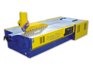
Dyna Pro’s range identifies the motorcycle S68 and S125 and the motorcycle/kart/ATV T62 as inertia-only models, with corresponding LC versions offering eddy-current load control. The S68 illustration above is the inertia-only model. A combined machine can still use inertia during a sweep, but its controller also has to account for the absorber’s load; do not treat the two configurations as interchangeable.