Removed text is struck through; added text is highlighted.
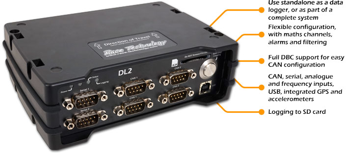
Industrial and vehicle-testing data logger with GPS, accelerometers, sensor inputs and SD data storage.
Image: Race Technology, reproduced with permission; manufacturer source.
Specifications and capabilities
The manufacturer lists 5 Hz GPS, 12 analogue channels, four frequency inputs, CAN and serial interfaces, with higher-rate and other options available. Confirm fitted options and card compatibility. Manufacturer specifications and documentation.
Data analysis software
Load a recorded DL2 run into Race Technology Analysis to plot channels and review the results. The manufacturer’s loading guide covers local storage and connected devices. Manufacturer documentation.
Race Technology Analysis example; the available channels and video depend on the recording and enabled options. Image: Race Technology, reproduced with permission; manufacturer source.
Download Race Technology software for Windows. Check the current version and any licence or hardware requirements; some advanced functions require a unit-linked licence. See the Race Technology software overview for features and licensing.
Pin / terminalFunction2CAN low3 and 6Ground7CAN high9+V input/output
On the 25-way analogue connector the manufacturer lists pins 1–8 for ADC 1–8, pins 9–12 for ADC 9–12 / outputs 1–4, and pins 14–25 as ground. Pin 13 is not assigned in the cited table; consult the source for all connectors and orientation.
Manufacturer connection reference.
Check the connector number, version and options on the actual unit against the manufacturer's documentation before wiring. Disconnect power before changing connections.
Wiring overview
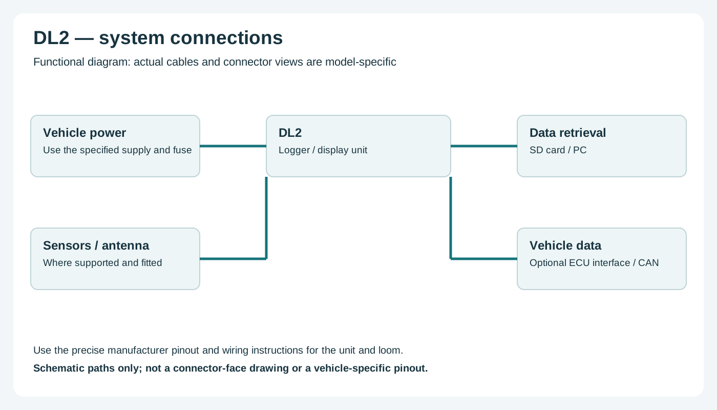
Functional wiring overview; not a connector-face diagram. Confirm actual connections with the manufacturer.
Return to the Race Technology manufacturer page.
Rendered revisions
Open each version to inspect formatting, tables and photographs.
Revision 2: Race Technology DL2
Industrial and vehicle-testing data logger with GPS, accelerometers, sensor inputs and SD data storage.
The manufacturer lists 5 Hz GPS, 12 analogue channels, four frequency inputs, CAN and serial interfaces, with higher-rate and other options available. Confirm fitted options and card compatibility. Manufacturer specifications and documentation.
Data analysis software
Load a recorded DL2 run into Race Technology Analysis to plot channels and review the results. The manufacturer’s loading guide covers local storage and connected devices. Manufacturer documentation.
Race Technology Analysis example; the available channels and video depend on the recording and enabled options. Image: Race Technology, reproduced with permission; manufacturer source.
On the 25-way analogue connector the manufacturer lists pins 1–8 for ADC 1–8, pins 9–12 for ADC 9–12 / outputs 1–4, and pins 14–25 as ground. Pin 13 is not assigned in the cited table; consult the source for all connectors and orientation.
Check the connector number, version and options on the actual unit against the manufacturer's documentation before wiring. Disconnect power before changing connections.
Wiring overview
Functional wiring overview; not a connector-face diagram. Confirm actual connections with the manufacturer.
The manufacturer lists 5 Hz GPS, 12 analogue channels, four frequency inputs, CAN and serial interfaces, with higher-rate and other options available. Confirm fitted options and card compatibility. Manufacturer specifications and documentation.
Data analysis software
Load a recorded DL2 run into Race Technology Analysis to plot channels and review the results. The manufacturer’s loading guide covers local storage and connected devices. Manufacturer documentation.
Race Technology Analysis example; the available channels and video depend on the recording and enabled options. Image: Race Technology, reproduced with permission; manufacturer source.
On the 25-way analogue connector the manufacturer lists pins 1–8 for ADC 1–8, pins 9–12 for ADC 9–12 / outputs 1–4, and pins 14–25 as ground. Pin 13 is not assigned in the cited table; consult the source for all connectors and orientation.
Check the connector number, version and options on the actual unit against the manufacturer's documentation before wiring. Disconnect power before changing connections.
Wiring overview
Functional wiring overview; not a connector-face diagram. Confirm actual connections with the manufacturer.