Removed text is struck through; added text is highlighted.
Bosch DDU 11 combines a 6.5-inch programmable display with 4 GB basic logging of 100 channels at 20 Hz. Full logging, a second partition, USB recording and external GPS are options. Additional inputs depend on IO_EXTENS. Bosch DDU 11 specification.
Bosch Motorsport DDU 11 display logger. Image: Bosch Motorsport, reproduced with permission; manufacturer source.
Data analysis software
WinDarab V7 example showing lap traces and circuit map. Image: Bosch Motorsport, reproduced with permission; manufacturer product page.
Bosch lists the DDU 11 among WinDarab-supported devices. Use WinDarab V7 on a PC to examine downloaded logged channels, compare measurements and review traces. The available channels and transfer method depend on the DDU 11's configuration and enabled options. Bosch supported devices.
WinDarab V7 download, documentation and edition information. RaceCon is a separate configuration tool for compatible devices. See the Bosch Motorsport software overview.
Connector and pinout
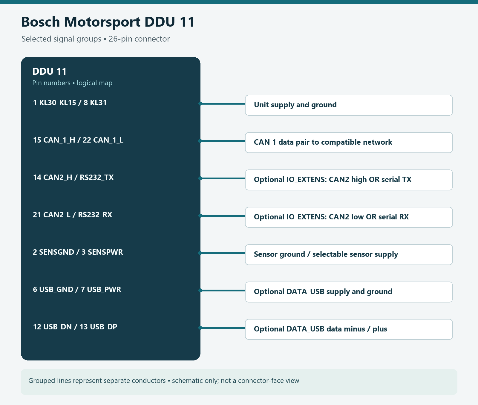
Mating connector TE 3-1437290-7, terminals 3-1447221-4. Pins 14/21 can be CAN 2 or RS232 and require IO_EXTENS. USB pins require DATA_USB. Identify cavities by the manufacturer's diagram and the actual connector. Bosch product pin configuration.
Original wiki illustration of selected DDU 11 signal groups, not a physical connector-face drawing. Grouped lines represent separate conductors. Source: Bosch Motorsport DDU 11 pin configuration. Check the full connector table and manufacturer diagram.
PinSignal (Bosch designation)Availability1KL30_KL15/UBATIncluded2SENSGNDIncluded3SENSPWR (5 V or UBAT switched)Included4SIG2_INIO_EXTENS5SIG4_INIO_EXTENS6USB_GNDDATA_USB7USB_PWRDATA_USB8KL31/GNDIncluded9SIG5_IN_LAPTRGIO_EXTENS10SIG1_INIO_EXTENS11SIG3_INIO_EXTENS12USB_DNDATA_USB13USB_DPDATA_USB14CAN_2_H_RS232_TXIO_EXTENS15CAN_1_HIncluded16ETH_CHANNEL0_TXNIncluded17ETH_CHANNEL0_TXPIncluded18ETH_CHANNEL0_RXNIncluded19ETH_CHANNEL0_RXPIncluded20TIMESTMP_INOUTIncluded21CAN_2_L_RS232_RXIO_EXTENS22CAN_1_LIncluded23ETH_CHANNEL1_TXNIncluded24ETH_CHANNEL1_TXPIncluded25ETH_CHANNEL1_RXNIncluded26ETH_CHANNEL1_RXPIncluded
Installation and related information
Confirm the precise model, hardware revision, enabled options and manufacturer's wiring diagram before connecting. Use correct power protection, sensor limits and the chosen ECU protocol; a compatible connector does not guarantee compatible data. Configure in the appropriate Bosch software and verify a short recording or connection. See the Bosch Motorsport manufacturer overview.
Rendered revisions
Open each version to inspect formatting, tables and photographs.
Revision 2: Bosch Motorsport DDU 11
Bosch DDU 11 combines a 6.5-inch programmable display with 4 GB basic logging of 100 channels at 20 Hz. Full logging, a second partition, USB recording and external GPS are options. Additional inputs depend on IO_EXTENS. Bosch DDU 11 specification.
Bosch Motorsport DDU 11 display logger. Image: Bosch Motorsport, reproduced with permission; manufacturer source.
Data analysis software
WinDarab V7 example showing lap traces and circuit map. Image: Bosch Motorsport, reproduced with permission; manufacturer product page.
Bosch lists the DDU 11 among WinDarab-supported devices. Use WinDarab V7 on a PC to examine downloaded logged channels, compare measurements and review traces. The available channels and transfer method depend on the DDU 11's configuration and enabled options. Bosch supported devices.
Mating connector TE 3-1437290-7, terminals 3-1447221-4. Pins 14/21 can be CAN 2 or RS232 and require IO_EXTENS. USB pins require DATA_USB. Identify cavities by the manufacturer's diagram and the actual connector. Bosch product pin configuration.
Original wiki illustration of selected DDU 11 signal groups, not a physical connector-face drawing. Grouped lines represent separate conductors. Source: Bosch Motorsport DDU 11 pin configuration. Check the full connector table and manufacturer diagram.
Pin
Signal (Bosch designation)
Availability
1
KL30_KL15/UBAT
Included
2
SENSGND
Included
3
SENSPWR (5 V or UBAT switched)
Included
4
SIG2_IN
IO_EXTENS
5
SIG4_IN
IO_EXTENS
6
USB_GND
DATA_USB
7
USB_PWR
DATA_USB
8
KL31/GND
Included
9
SIG5_IN_LAPTRG
IO_EXTENS
10
SIG1_IN
IO_EXTENS
11
SIG3_IN
IO_EXTENS
12
USB_DN
DATA_USB
13
USB_DP
DATA_USB
14
CAN_2_H_RS232_TX
IO_EXTENS
15
CAN_1_H
Included
16
ETH_CHANNEL0_TXN
Included
17
ETH_CHANNEL0_TXP
Included
18
ETH_CHANNEL0_RXN
Included
19
ETH_CHANNEL0_RXP
Included
20
TIMESTMP_INOUT
Included
21
CAN_2_L_RS232_RX
IO_EXTENS
22
CAN_1_L
Included
23
ETH_CHANNEL1_TXN
Included
24
ETH_CHANNEL1_TXP
Included
25
ETH_CHANNEL1_RXN
Included
26
ETH_CHANNEL1_RXP
Included
Installation and related information
Confirm the precise model, hardware revision, enabled options and manufacturer's wiring diagram before connecting. Use correct power protection, sensor limits and the chosen ECU protocol; a compatible connector does not guarantee compatible data. Configure in the appropriate Bosch software and verify a short recording or connection. See the Bosch Motorsport manufacturer overview.
Revision 2: Bosch Motorsport DDU 11
Bosch DDU 11 combines a 6.5-inch programmable display with 4 GB basic logging of 100 channels at 20 Hz. Full logging, a second partition, USB recording and external GPS are options. Additional inputs depend on IO_EXTENS. Bosch DDU 11 specification.
Bosch Motorsport DDU 11 display logger. Image: Bosch Motorsport, reproduced with permission; manufacturer source.
Data analysis software
WinDarab V7 example showing lap traces and circuit map. Image: Bosch Motorsport, reproduced with permission; manufacturer product page.
Bosch lists the DDU 11 among WinDarab-supported devices. Use WinDarab V7 on a PC to examine downloaded logged channels, compare measurements and review traces. The available channels and transfer method depend on the DDU 11's configuration and enabled options. Bosch supported devices.
Mating connector TE 3-1437290-7, terminals 3-1447221-4. Pins 14/21 can be CAN 2 or RS232 and require IO_EXTENS. USB pins require DATA_USB. Identify cavities by the manufacturer's diagram and the actual connector. Bosch product pin configuration.
Original wiki illustration of selected DDU 11 signal groups, not a physical connector-face drawing. Grouped lines represent separate conductors. Source: Bosch Motorsport DDU 11 pin configuration. Check the full connector table and manufacturer diagram.
Pin
Signal (Bosch designation)
Availability
1
KL30_KL15/UBAT
Included
2
SENSGND
Included
3
SENSPWR (5 V or UBAT switched)
Included
4
SIG2_IN
IO_EXTENS
5
SIG4_IN
IO_EXTENS
6
USB_GND
DATA_USB
7
USB_PWR
DATA_USB
8
KL31/GND
Included
9
SIG5_IN_LAPTRG
IO_EXTENS
10
SIG1_IN
IO_EXTENS
11
SIG3_IN
IO_EXTENS
12
USB_DN
DATA_USB
13
USB_DP
DATA_USB
14
CAN_2_H_RS232_TX
IO_EXTENS
15
CAN_1_H
Included
16
ETH_CHANNEL0_TXN
Included
17
ETH_CHANNEL0_TXP
Included
18
ETH_CHANNEL0_RXN
Included
19
ETH_CHANNEL0_RXP
Included
20
TIMESTMP_INOUT
Included
21
CAN_2_L_RS232_RX
IO_EXTENS
22
CAN_1_L
Included
23
ETH_CHANNEL1_TXN
Included
24
ETH_CHANNEL1_TXP
Included
25
ETH_CHANNEL1_RXN
Included
26
ETH_CHANNEL1_RXP
Included
Installation and related information
Confirm the precise model, hardware revision, enabled options and manufacturer's wiring diagram before connecting. Use correct power protection, sensor limits and the chosen ECU protocol; a compatible connector does not guarantee compatible data. Configure in the appropriate Bosch software and verify a short recording or connection. See the Bosch Motorsport manufacturer overview.