Removed text is struck through; added text is highlighted.
EDL-1 is a compact ECU serial data logger for ECUMASTER EMU Classic and EMU Black. It records over 200 channels at 25 Hz to a compatible FAT32 SDHC card and has Bluetooth and a battery-backed real-time clock. It does not work with EMU PRO, which logs directly to USB. Sources: product page and EDL-1 manual.
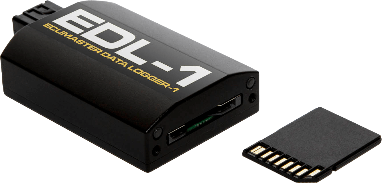
ECUMASTER EDL-1 logger and SD card. Image: ECUMASTER; reproduced with permission. Manufacturer source.
Data analysis software
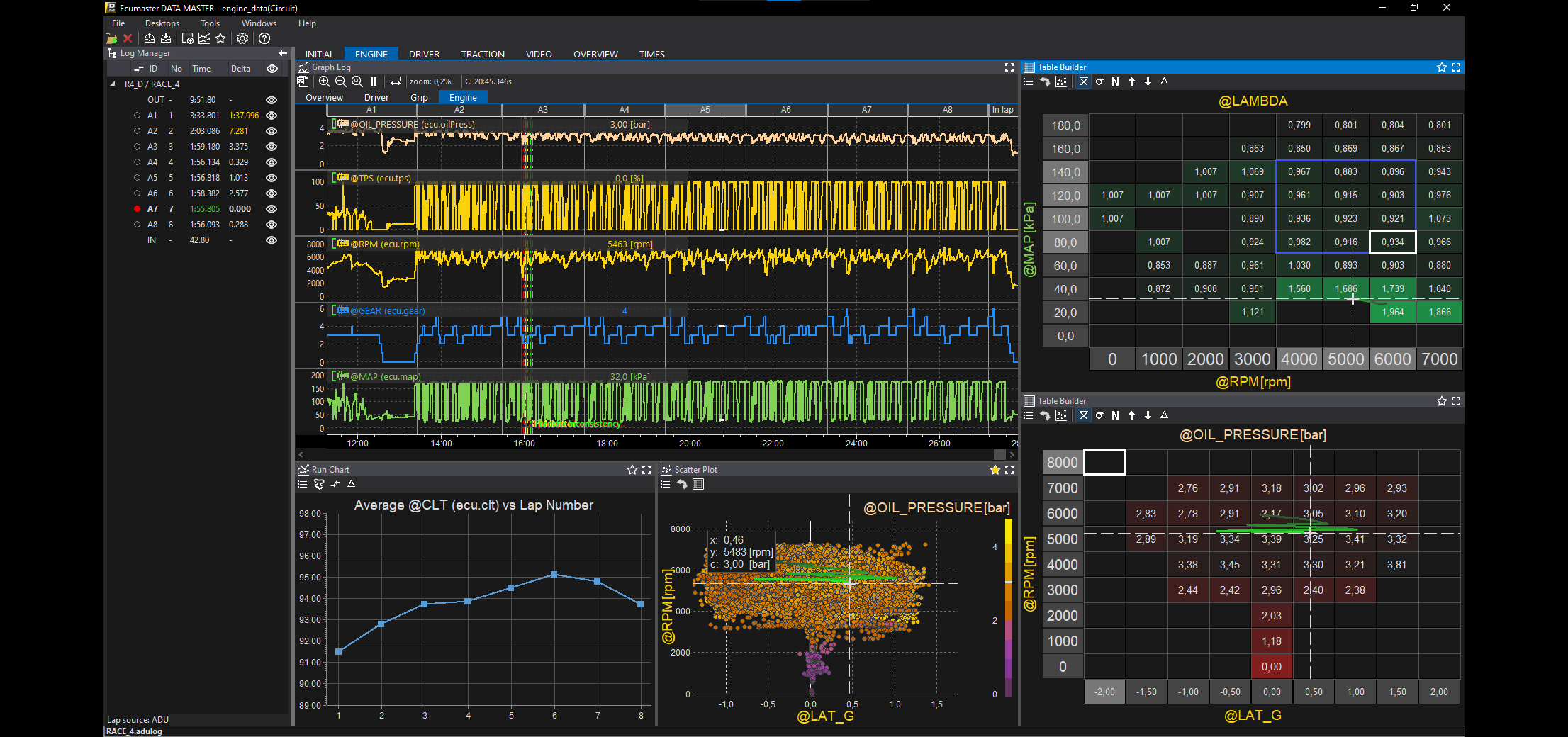
Data Master 2024.4 analysis showing channel traces, scatter plot and tables. Image: ECUMASTER, reproduced with permission; manufacturer release announcement.
Transfer the EDL-1 recording from its SD card to a PC and open it in ECUMASTER Data Master to graph logged channels and analyse runs. ECUMASTER lists EDL-1 among the supported loggers. Download Data Master and its manual; see the EDL-1 manual for its recording and card requirements. Channels depend on the connected compatible EMU and configuration.
See the ECUMASTER analysis software overview.
Specifications
The manufacturer’s manual v2.8 lists 5–20 V operating supply, 64 × 45 × 18 mm, 50 g, −40 to +85 °C, two status LEDs and FAT32 SDHC cards up to 32 GB. Card and firmware compatibility should be checked against the current supported-card list. Bluetooth supports local live data and is not itself remote telemetry.
Connector and pinout
The manual identifies Molex 34793-0040 and shows the connector face, pin 1 left to pin 4 right. Verify actual component markings and orientation. EDL-1 manual, installation section.
PinFunction1Ground2RXD3TXD4Power supply
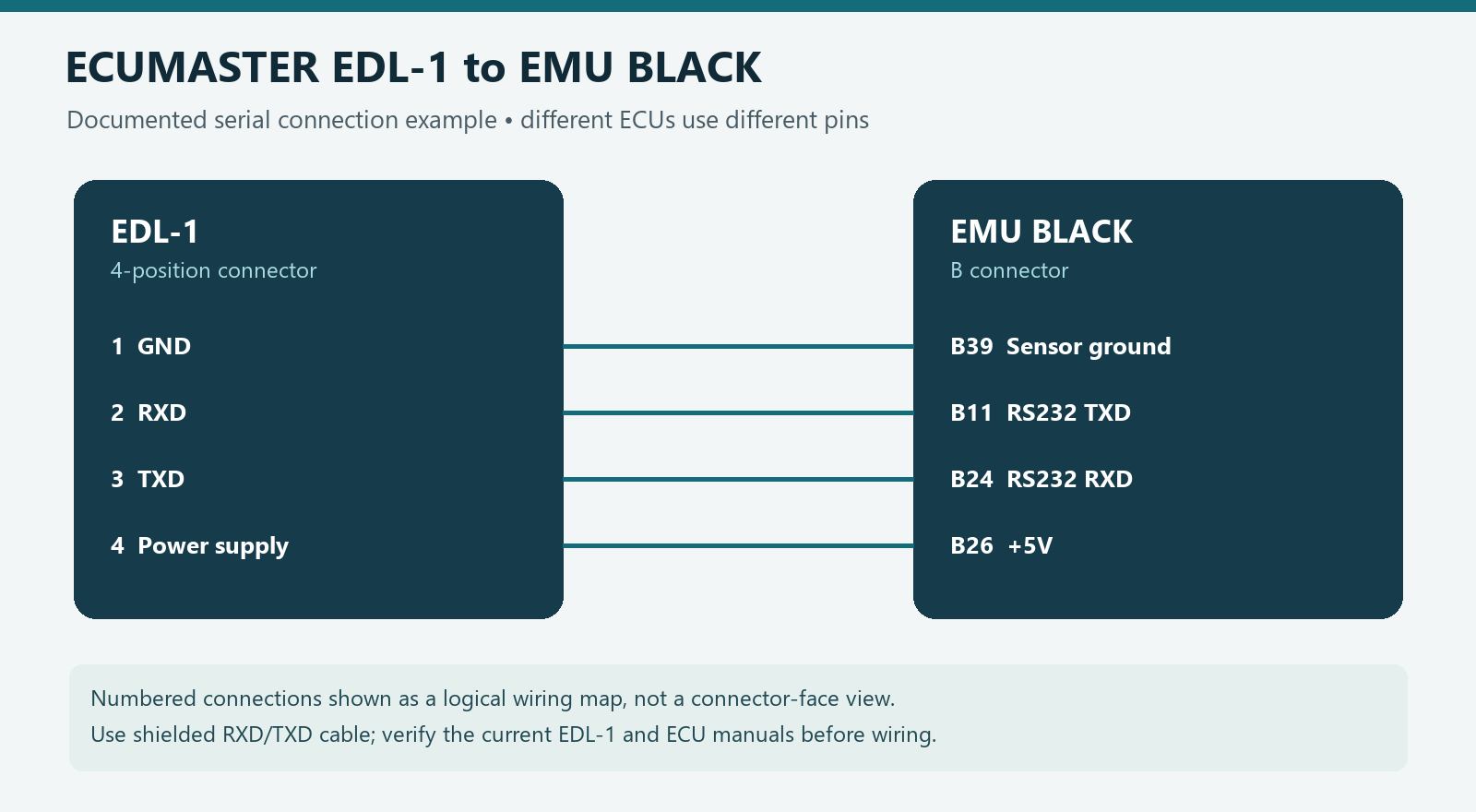
Original wiki wiring illustration of the EDL-1 to EMU BLACK example; this is a logical diagram, not a connector-face view. Source: ECUMASTER EDL-1 manual, installation section. Verify the exact ECU and connector before wiring.
Wiring
For the manufacturer’s EMU BLACK example, EDL pins 1–4 connect respectively to ECU B39 sensor ground, B11 RS232 TXD, B24 RS232 RXD and B26 +5 V. For the documented EMU Classic example, pins 1–4 connect to ECU pins 4 ground, 2 TXD, 1 RXD and 5 +5 V. ECUMASTER calls for shielded RXD/TXD and also documents an external 12 V and ground option. Check supply capacity, ECU revision and the manual before wiring; do not substitute an unverified ECU pinout.
Manufacturer overview: ECUMASTER dataloggers and displays. Confirm revision, loom, connector and options before installation.
Rendered revisions
Open each version to inspect formatting, tables and photographs.
Revision 2: ECUMASTER EDL-1
EDL-1 is a compact ECU serial data logger for ECUMASTER EMU Classic and EMU Black. It records over 200 channels at 25 Hz to a compatible FAT32 SDHC card and has Bluetooth and a battery-backed real-time clock. It does not work with EMU PRO, which logs directly to USB. Sources: product page and EDL-1 manual.
ECUMASTER EDL-1 logger and SD card. Image: ECUMASTER; reproduced with permission. Manufacturer source.
Data analysis software
Data Master 2024.4 analysis showing channel traces, scatter plot and tables. Image: ECUMASTER, reproduced with permission; manufacturer release announcement.
Transfer the EDL-1 recording from its SD card to a PC and open it in ECUMASTER Data Master to graph logged channels and analyse runs. ECUMASTER lists EDL-1 among the supported loggers. Download Data Master and its manual; see the EDL-1 manual for its recording and card requirements. Channels depend on the connected compatible EMU and configuration.
The manufacturer’s manual v2.8 lists 5–20 V operating supply, 64 × 45 × 18 mm, 50 g, −40 to +85 °C, two status LEDs and FAT32 SDHC cards up to 32 GB. Card and firmware compatibility should be checked against the current supported-card list. Bluetooth supports local live data and is not itself remote telemetry.
Connector and pinout
The manual identifies Molex 34793-0040 and shows the connector face, pin 1 left to pin 4 right. Verify actual component markings and orientation. EDL-1 manual, installation section.
Pin
Function
1
Ground
2
RXD
3
TXD
4
Power supply
Original wiki wiring illustration of the EDL-1 to EMU BLACK example; this is a logical diagram, not a connector-face view. Source: ECUMASTER EDL-1 manual, installation section. Verify the exact ECU and connector before wiring.
Wiring
For the manufacturer’s EMU BLACK example, EDL pins 1–4 connect respectively to ECU B39 sensor ground, B11 RS232 TXD, B24 RS232 RXD and B26 +5 V. For the documented EMU Classic example, pins 1–4 connect to ECU pins 4 ground, 2 TXD, 1 RXD and 5 +5 V. ECUMASTER calls for shielded RXD/TXD and also documents an external 12 V and ground option. Check supply capacity, ECU revision and the manual before wiring; do not substitute an unverified ECU pinout.
EDL-1 is a compact ECU serial data logger for ECUMASTER EMU Classic and EMU Black. It records over 200 channels at 25 Hz to a compatible FAT32 SDHC card and has Bluetooth and a battery-backed real-time clock. It does not work with EMU PRO, which logs directly to USB. Sources: product page and EDL-1 manual.
ECUMASTER EDL-1 logger and SD card. Image: ECUMASTER; reproduced with permission. Manufacturer source.
Data analysis software
Data Master 2024.4 analysis showing channel traces, scatter plot and tables. Image: ECUMASTER, reproduced with permission; manufacturer release announcement.
Transfer the EDL-1 recording from its SD card to a PC and open it in ECUMASTER Data Master to graph logged channels and analyse runs. ECUMASTER lists EDL-1 among the supported loggers. Download Data Master and its manual; see the EDL-1 manual for its recording and card requirements. Channels depend on the connected compatible EMU and configuration.
The manufacturer’s manual v2.8 lists 5–20 V operating supply, 64 × 45 × 18 mm, 50 g, −40 to +85 °C, two status LEDs and FAT32 SDHC cards up to 32 GB. Card and firmware compatibility should be checked against the current supported-card list. Bluetooth supports local live data and is not itself remote telemetry.
Connector and pinout
The manual identifies Molex 34793-0040 and shows the connector face, pin 1 left to pin 4 right. Verify actual component markings and orientation. EDL-1 manual, installation section.
Pin
Function
1
Ground
2
RXD
3
TXD
4
Power supply
Original wiki wiring illustration of the EDL-1 to EMU BLACK example; this is a logical diagram, not a connector-face view. Source: ECUMASTER EDL-1 manual, installation section. Verify the exact ECU and connector before wiring.
Wiring
For the manufacturer’s EMU BLACK example, EDL pins 1–4 connect respectively to ECU B39 sensor ground, B11 RS232 TXD, B24 RS232 RXD and B26 +5 V. For the documented EMU Classic example, pins 1–4 connect to ECU pins 4 ground, 2 TXD, 1 RXD and 5 +5 V. ECUMASTER calls for shielded RXD/TXD and also documents an external 12 V and ground option. Check supply capacity, ECU revision and the manual before wiring; do not substitute an unverified ECU pinout.