Removed text is struck through; added text is highlighted.
MoTeC CDL3 (MoTeC part #18022) is a motorsport display and acquisition device. The information here is specific to the cited part; check the label, hardware revision, options and vehicle protocol before connection.
MoTeC CDL3. Image: MoTeC, reproduced with permission. Manufacturer product page and specifications.
Specifications and options
Backlit monochrome display with a 70-segment bar graph and 13-character text bar, configurable pages and alerts.Logging is optional: the data-logging upgrade adds 8 MB storage, with logging rates up to 500 samples per second.Two configurable CAN or RS232 buses and a dedicated RS232 connection; additional analogue, temperature and auxiliary functions depend on the I/O upgrade.Configuration is performed with MoTeC software; match the ECU interface and enabled options before installation.
Connector and pinout
34-way AMP: the table below follows the manufacturer’s pinout for part #18022. Check cavity numbering and the manufacturer's connector view; the functional map is not a physical connector-face drawing. Blank cells retain the source's unspecified function; do not assign them by assumption. Inputs marked as optional need the appropriate enabled upgrade.
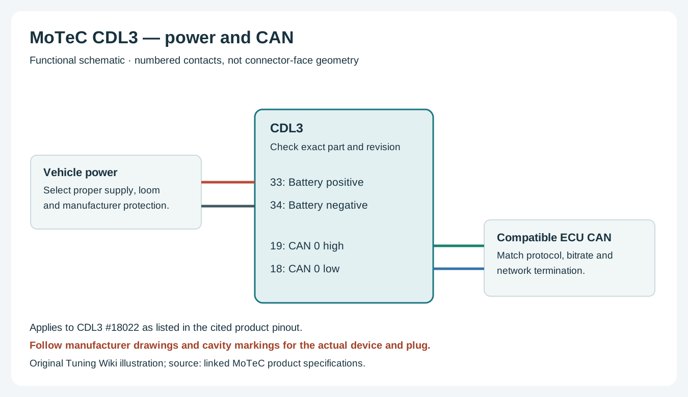
Power and CAN example, functional schematic rather than connector geometry. Original Tuning Wiki illustration based on the MoTeC product pinout; verify the actual harness and matching ECU.
Use the correct connector, power and sensor return for this unit. Match CAN high and low to a compatible, correctly configured network and check existing termination. ECU channels, sensors and lap timing depend on the specific hardware, protocol, configuration and licensed options. Use manufacturer instructions for wire gauge, supply protection and continuity checks; do not connect vehicle battery voltage to a sensor reference output.
MoTeC i2 supports reviewing recorded data; Pro analysis and T2 telemetry require the applicable upgrades. A telemetry licence alone does not provide a radio or cellular connection. See the MoTeC manufacturer guide for family comparisons and references.
Data analysis software
MoTeC i2 data analysis showing channel traces and gauges. Image: MoTeC, reproduced with permission; manufacturer image.
The CDL3 needs its applicable data-logging upgrade or a logging-equipped kit before it can produce recordings for analysis. MoTeC i2 reviews recorded channels in graphs and reports; i2 Pro features depend on the device upgrade or applicable software licence. See the manufacturer model and analysis comparison and i2 software and licence information.
Retrieve a recording with the compatible MoTeC device manager, then open it in i2 to compare channels and laps when suitable position data has been recorded. Download MoTeC software from the official downloads library; see the MoTeC manufacturer guide for the Standard and Pro options.
Rendered revisions
Open each version to inspect formatting, tables and photographs.
Revision 2: MoTeC CDL3
MoTeC CDL3 (MoTeC part #18022) is a motorsport display and acquisition device. The information here is specific to the cited part; check the label, hardware revision, options and vehicle protocol before connection.
Backlit monochrome display with a 70-segment bar graph and 13-character text bar, configurable pages and alerts.
Logging is optional: the data-logging upgrade adds 8 MB storage, with logging rates up to 500 samples per second.
Two configurable CAN or RS232 buses and a dedicated RS232 connection; additional analogue, temperature and auxiliary functions depend on the I/O upgrade.
Configuration is performed with MoTeC software; match the ECU interface and enabled options before installation.
Connector and pinout
34-way AMP: the table below follows the manufacturer’s pinout for part #18022. Check cavity numbering and the manufacturer's connector view; the functional map is not a physical connector-face drawing. Blank cells retain the source's unspecified function; do not assign them by assumption. Inputs marked as optional need the appropriate enabled upgrade.
Pin
Name
Standard function
Optional function
1
E-TX-
Ethernet Transmit -
2
E-TX+
Ethernet Transmit +
3
AV1
Analogue Voltage Input 1
4
AV2
Analogue Voltage Input 2
5
AV3
Analogue Voltage Input 3
6
AV4
Analogue Voltage Input 4
7
8V
Sensor 8 V
8
5V
Sensor 5 V
9
0V
Sensor 0 V
10
E-RX-
Ethernet Receive -
11
E-RX+
Ethernet Receive +
12
13
14
DIG1
Alarm Ack*
Digital Input 1
15
DIG2
Next Line*
Digital Input 2
16
AT1
Analogue Temp Input 1
17
AT2
Analogue Temp Input 2
18
CAN0L / RS232 0 GND
CAN0 Lo / RS232 0 GND
19
CAN0H / RS232 0 RX
CAN0 Hi / RS232 0 RX
20
TX
RS232 Output
21
SPD1
Speed Input 1
22
SPD2
Speed Input 2
23
SPD3
Brightness Switch
Speed Input 3
24
25
26
CAN1L / RS232 1 GND
CAN1 Lo / RS232 1 GND
27
CAN1H / RS232 1 RX
CAN1 Hi / RS232 1 RX
28
RX
RS232 Input
29
AUX1
Auxiliary Output 1
30
AUX2
Auxiliary Output 2
31
AUX3
Auxiliary Output 3
32
AUX4
Auxiliary Output 4
33
BAT+
Battery Positive
34
BAT-
Battery Negative
Wiring and configuration
Power and CAN example, functional schematic rather than connector geometry. Original Tuning Wiki illustration based on the MoTeC product pinout; verify the actual harness and matching ECU.
Use the correct connector, power and sensor return for this unit. Match CAN high and low to a compatible, correctly configured network and check existing termination. ECU channels, sensors and lap timing depend on the specific hardware, protocol, configuration and licensed options. Use manufacturer instructions for wire gauge, supply protection and continuity checks; do not connect vehicle battery voltage to a sensor reference output.
MoTeC i2 supports reviewing recorded data; Pro analysis and T2 telemetry require the applicable upgrades. A telemetry licence alone does not provide a radio or cellular connection. See the MoTeC manufacturer guide for family comparisons and references.
Data analysis software
MoTeC i2 data analysis showing channel traces and gauges. Image: MoTeC, reproduced with permission; manufacturer image.
The CDL3 needs its applicable data-logging upgrade or a logging-equipped kit before it can produce recordings for analysis. MoTeC i2 reviews recorded channels in graphs and reports; i2 Pro features depend on the device upgrade or applicable software licence. See the manufacturer model and analysis comparison and i2 software and licence information.
MoTeC CDL3 (MoTeC part #18022) is a motorsport display and acquisition device. The information here is specific to the cited part; check the label, hardware revision, options and vehicle protocol before connection.
Backlit monochrome display with a 70-segment bar graph and 13-character text bar, configurable pages and alerts.
Logging is optional: the data-logging upgrade adds 8 MB storage, with logging rates up to 500 samples per second.
Two configurable CAN or RS232 buses and a dedicated RS232 connection; additional analogue, temperature and auxiliary functions depend on the I/O upgrade.
Configuration is performed with MoTeC software; match the ECU interface and enabled options before installation.
Connector and pinout
34-way AMP: the table below follows the manufacturer’s pinout for part #18022. Check cavity numbering and the manufacturer's connector view; the functional map is not a physical connector-face drawing. Blank cells retain the source's unspecified function; do not assign them by assumption. Inputs marked as optional need the appropriate enabled upgrade.
Pin
Name
Standard function
Optional function
1
E-TX-
Ethernet Transmit -
2
E-TX+
Ethernet Transmit +
3
AV1
Analogue Voltage Input 1
4
AV2
Analogue Voltage Input 2
5
AV3
Analogue Voltage Input 3
6
AV4
Analogue Voltage Input 4
7
8V
Sensor 8 V
8
5V
Sensor 5 V
9
0V
Sensor 0 V
10
E-RX-
Ethernet Receive -
11
E-RX+
Ethernet Receive +
12
13
14
DIG1
Alarm Ack*
Digital Input 1
15
DIG2
Next Line*
Digital Input 2
16
AT1
Analogue Temp Input 1
17
AT2
Analogue Temp Input 2
18
CAN0L / RS232 0 GND
CAN0 Lo / RS232 0 GND
19
CAN0H / RS232 0 RX
CAN0 Hi / RS232 0 RX
20
TX
RS232 Output
21
SPD1
Speed Input 1
22
SPD2
Speed Input 2
23
SPD3
Brightness Switch
Speed Input 3
24
25
26
CAN1L / RS232 1 GND
CAN1 Lo / RS232 1 GND
27
CAN1H / RS232 1 RX
CAN1 Hi / RS232 1 RX
28
RX
RS232 Input
29
AUX1
Auxiliary Output 1
30
AUX2
Auxiliary Output 2
31
AUX3
Auxiliary Output 3
32
AUX4
Auxiliary Output 4
33
BAT+
Battery Positive
34
BAT-
Battery Negative
Wiring and configuration
Power and CAN example, functional schematic rather than connector geometry. Original Tuning Wiki illustration based on the MoTeC product pinout; verify the actual harness and matching ECU.
Use the correct connector, power and sensor return for this unit. Match CAN high and low to a compatible, correctly configured network and check existing termination. ECU channels, sensors and lap timing depend on the specific hardware, protocol, configuration and licensed options. Use manufacturer instructions for wire gauge, supply protection and continuity checks; do not connect vehicle battery voltage to a sensor reference output.
MoTeC i2 supports reviewing recorded data; Pro analysis and T2 telemetry require the applicable upgrades. A telemetry licence alone does not provide a radio or cellular connection. See the MoTeC manufacturer guide for family comparisons and references.
Data analysis software
MoTeC i2 data analysis showing channel traces and gauges. Image: MoTeC, reproduced with permission; manufacturer image.
The CDL3 needs its applicable data-logging upgrade or a logging-equipped kit before it can produce recordings for analysis. MoTeC i2 reviews recorded channels in graphs and reports; i2 Pro features depend on the device upgrade or applicable software licence. See the manufacturer model and analysis comparison and i2 software and licence information.